24 IFP-FFT Manual — P/N 54708:B3 10/28/2021
Audio Phone Circuit Installation Wiring Requirements for the Audio Telephone Circuit
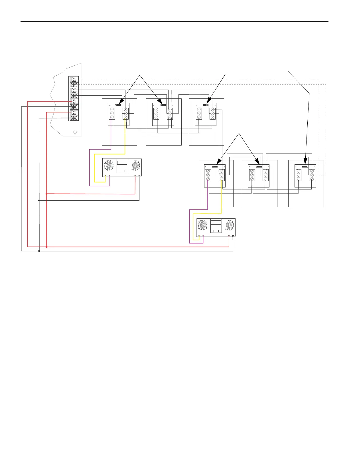
5.2.4 Multi-Phone Jack Audio Circuit in Class A Configuration
For wiring specifications, refer to Section 5.2. Figure 5.5 illustrates how to wire the multi-phone jack audio circuit and the SLC in Class A
configuration. In the multi-phone jack configuration, the maximum mini-monitor contact wiring resistance between the first and last FFT-
FPJ must be less that 100 ohms.
SLC OUT
+
–
+
–
+
+
PHONE
–
SLC
IN P H O N E IN
–
OUT
1 3
2 2
3 1
TB2
TB1
1 3
2 2
3 1
TB2
TB1
1 3
2 2
3 1
TB2
TB1
1 3
2 2
3 1
TB2
TB1
ADDRESS
LOOP
ONES
TENS
Contact EOL Connected
(See Figure 5.2 for EOL reference.)
Do not loop wire under the terminals.
Break wire run to provide proper
supervision of communications.
+ audio in
- audio in
+ audio out
- audio out
IFP-MINIMON
IFP-MINIMON
IFP-FFT
FFT-FPJFFT-FPJ
FFT-FPJ FFT-FPJ FFT-FPJ
FFT-FPJ
Contact EOL Not Connected
(See Figure 5.2 for EOL reference.)
+ SLC in
- SLC in
+ SLC out
- SLC out
Contact EOL Not Connected
(See Figure 5.2 for EOL reference.)
Class A wiring
Figure 5.5 Multi-Phone Jack Audio Circuit Wired in Class A Configuration
 Loading...