IFP-FFT Manual — P/N 54708:B3 10/28/2021 13
Wiring Specifications Installation
3.4 Wiring Specifications
Induced noise (the transfer of the electrical energy from one wire to another wire) can interfere with the telephone communication or it can
cause false alarms. To avoid induced noise, follow these guidelines:
• Isolate the input wiring from the high current output and power wiring. Do not pull one multi-conductor cable for the entire panel.
Instead, separate the wiring as follows:
– SLC loops
– Audio circuits
– Relay circuit
• Do not pull the wires from different groups through the same conduit. If you must run them together, do so for as short a distance as
possible or use the shielded cable. Twisted, shielded wire on the Audio Circuits is recommended for the maximum protection against
EMI and AFI emissions and susceptibility. Connect the shield to earth ground at the panel. You must route the high and low voltages
separately.
• Route the wiring around the inside perimeter of the cabinet. It should not cross the circuit board where it could induce noise into the
sensitive microelectronics or pick up unwanted RF noise from the high speed circuits. See Figure 3.9 for an example.
• High frequency noise, such as that produced by the inductive reactance of a speaker or bell, can also be reduced by running the wire
through ferrite shield beads or by wrapping it around a ferrite toroid.
3.5 Wire Routing
You must follow power-limited wiring techniques, which includes maintaining 0.25” spacing between power-limited and non-power-limited
circuits, and separating high and low voltage circuits.
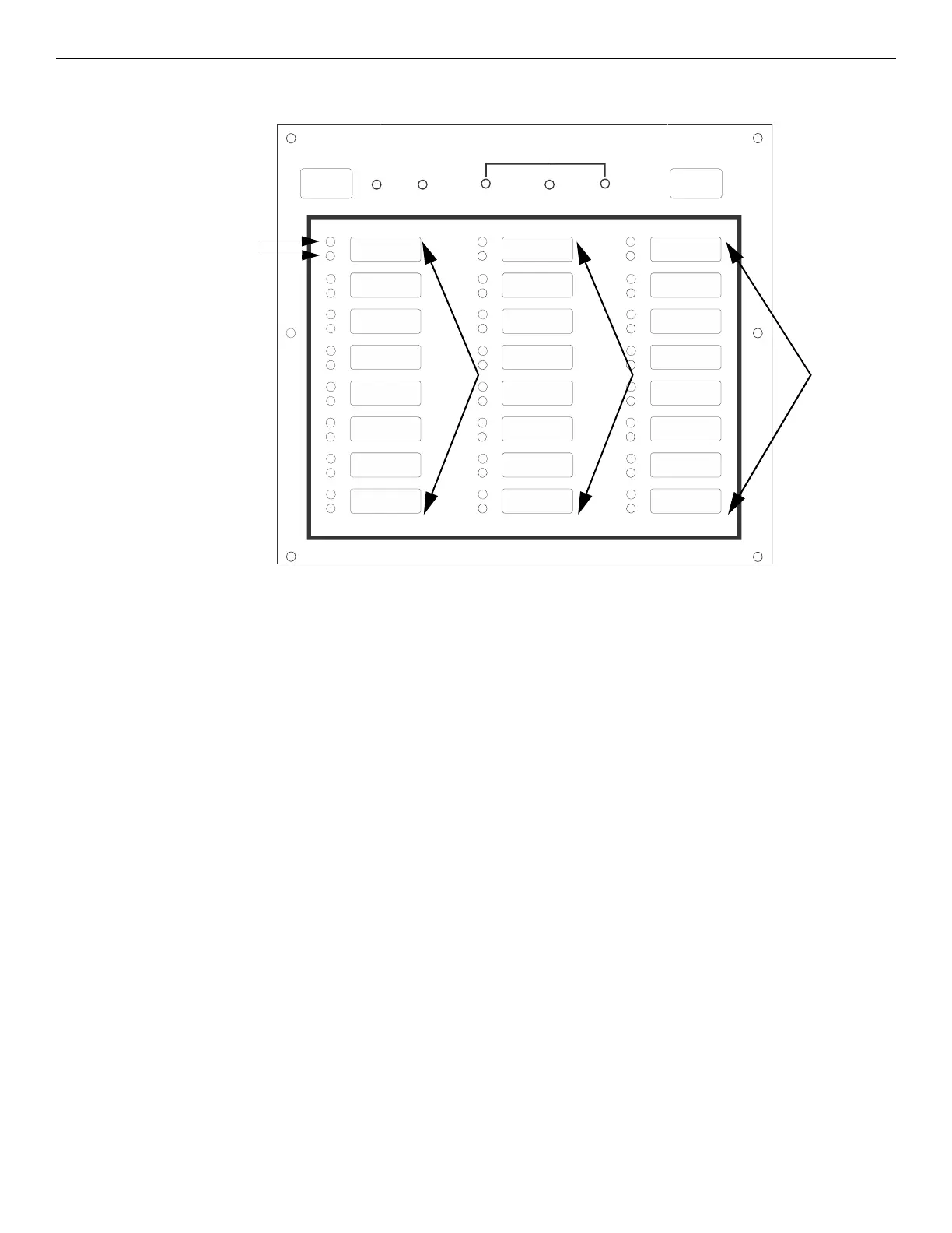
LOC AL
HANDSET
REMOTE
HANDSET
TROUBLE
POWERANSWER
GENERAL
active (green)
trouble (amber)
Zone 1-
Zone 8
Zone 9 -
Zone 16
Answer
LED
General
Trouble LED
Zone 17 -
Zone 24
Figure 3.8 IFP-FFT Front View
Power
LED
 Loading...