18 IFP-FFT Manual — P/N 54708:B3 10/28/2021
Installation FFT-STS Installation
3.12 FFT-STS Installation
The Single Telephone Station includes a series of parts. The following parts are ordered separately. Up to ten remote handsets may be oper-
ated simultaneously.
• telephone chassis
• backbox
• break glass kit
• door with keylock
3.12.1 Assembly of Units with Coiled Cord Handsets
The following procedure describes the steps required to assemble the telephones with the coiled cord handsets. These steps must be accom-
plished once the enclosure has been mounted and the system wiring is in place.
1. Attach the system wiring to the terminal strip on the telephone chassis assembly.
2. Install the 6-32 nuts in the backbox. Do not tighten the nuts.
3. Install the telephone chassis assembly in the backbox.
4. Install the trim ring on the backbox with 6-32 wing nuts. Do not tighten.
5. Install the door assembly. Tighten the wing nuts.
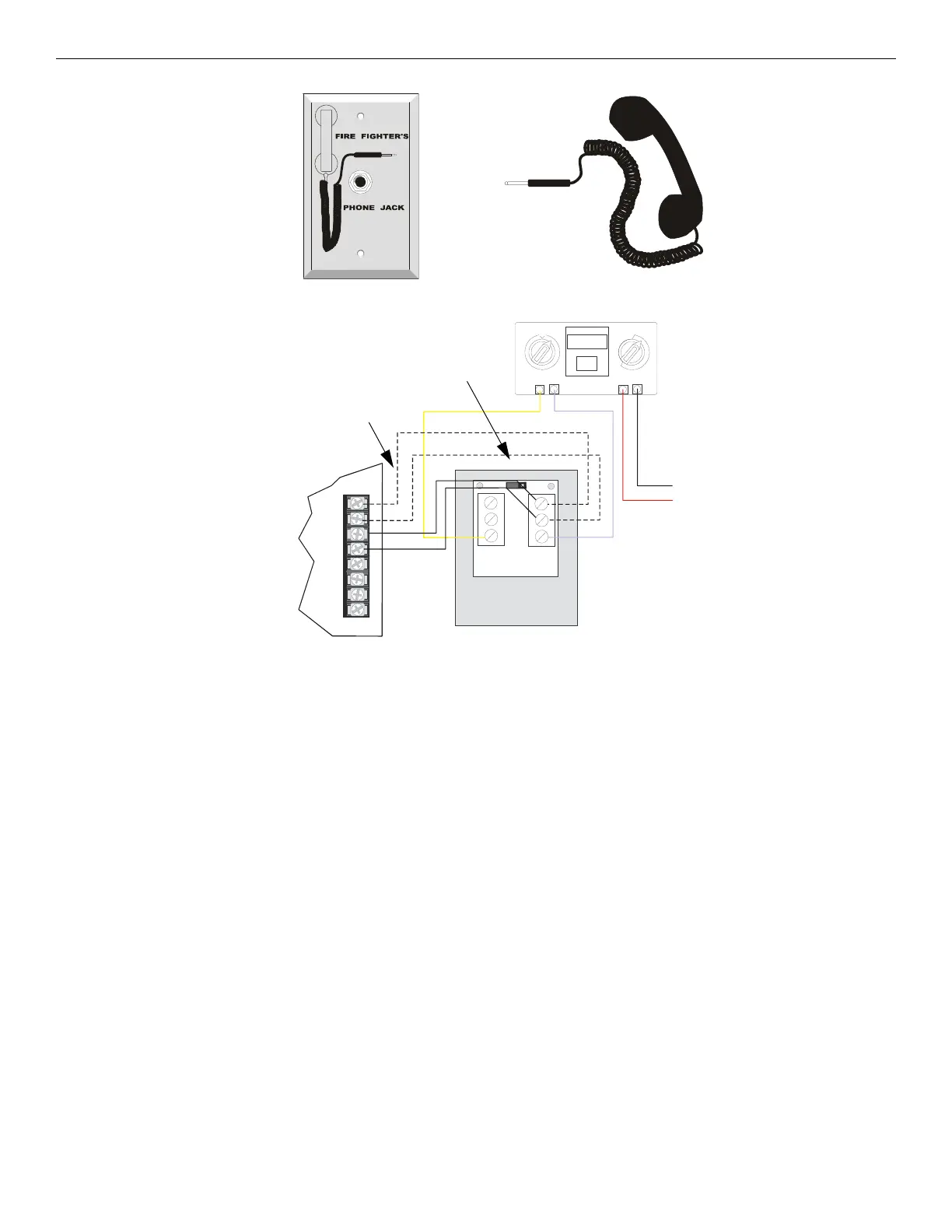
Figure 3.16 FFT-FPJ (Phone Jack) and FFT-RHS (Handset)
0
10
11
12
13
14
15
ADDRESS
LOOP
1
2
3
4
TENS
ONES
6
7
8
9
5
TB1
TB2
3
2
1
1
2
3
+ -
+
-
SLC
PHONE
PHONE
O
UT
OUT
IN
IN
SLC
- + - + - + - +
The Contact EOL is set to connected.
See Figure 3.19 for EOL reference.
IFP-FFT
FFT-FPJ
audio
audio
Class A wiring
Contact EOL
connected
4.7kΩ,1/2W ELR (install
on last device for Class B
telephone circuit only.)
yellow purple
to
SLC
Figure 3.17 IFP-FFT to FFT-FPJ Connection
 Loading...