–17–
Data Field Descriptions
Defaults (where applicable) are Indicated in Text.
The following pages list all data fields in this Control (in numerical order). Use the blank programming form
to record the data for this installation. Note that both keypad LEDs flash while in Programming mode.
Note: Entering a number other than the one specified will give unpredictable results.
✼
20
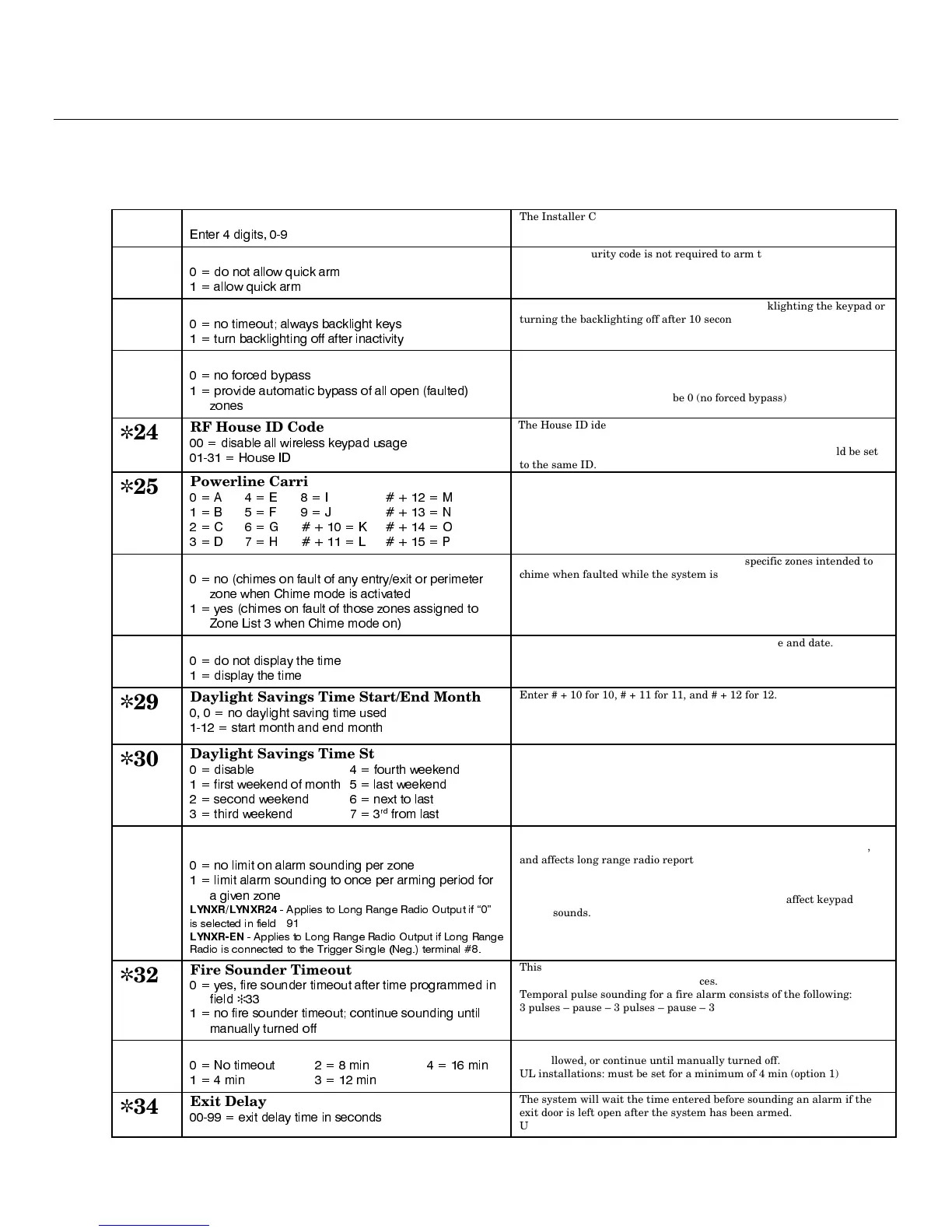
Installer Code
(QWHU GLJLWV
The Installer Code is used to enter the 4-digit Master Security Code. See
"Master Code" in the
System Operation
section
for procedure.
✼
21
Quick Arm Enable
GR QRW DOORZ TXLFN DUP
DOORZ TXLFN DUP
If enabled, security code is not required to arm the system. The user
simply presses and holds down the AWAY or STAY key to arm.
✼
22
Keypad Backlight Timeout
QR WLPHRXW DOZD\V EDFNOLJKW NH\V
WXUQ EDFNOLJKWLQJ RII DIWHU LQDFWLYLW\
This option allows the choice of either always backlighting the keypad or
turning the backlighting off after 10 seconds of keypad inactivity.
✼
23
Forced Bypass
QR IRUFHG E\SDVV
SURYLGH DXWRPDWLF E\SDVV RI DOO RSHQ IDXOWHG
]RQHV
All zones bypassed by this function will be displayed after the bypass is
initiated.
Note:
UL installations: must be 0 (no forced bypass)
✼
24
RF House ID Code
GLVDEOH DOO ZLUHOHVV NH\SDG XVDJH
+RXVH ,'
The House ID identifies receivers and wireless keypads.
If a 5827 Wireless Keypad or 5804BD/5804BDV Transmitter is to be
used, a House ID Code MUST be entered, and the keypad should be set
to the same ID.
✼
25
Powerline Carrier Device (X-10) House ID
$ ( , 0
% ) - 1
& * . 2
' + / 3
Powerline Carrier Devices require a House ID. This field identifies this
House ID to the Control. The Powerline Carrier Devices are
programmed in field ✻80.
✼
26
Chime by Zone
QR FKLPHV RQ IDXOW RI DQ\ HQWU\H[LW RU SHULPHWHU
]RQH ZKHQ &KLPH PRGH LV DFWLYDWHG
\HV FKLPHV RQ IDXOW RI WKRVH ]RQHV DVVLJQHG WR
=RQH /LVW ZKHQ &KLPH PRGH RQ
This option allows the installer to define the specific zones intended to
chime when faulted while the system is in Chime mode. If enabled, these
zones are defined in zone list 3 (see ✻81 Zone List Menu Mode).
✼
27
Real Time Clock Display
GR QRW GLVSOD\ WKH WLPH
GLVSOD\ WKH WLPH
Refer to the User’s Manual for setting the clock time and date.
✼
29
Daylight Savings Time Start/End Month
QR GD\OLJKW VDYLQJ WLPH XVHG
VWDUW PRQWK DQG HQG PRQWK
Enter # + 10 for 10, # + 11 for 11, and # + 12 for 12.
✼
30
Daylight Savings Time Start/End Week
GLVDEOH IRXUWK ZHHNHQG
ILUVW ZHHNHQG RI PRQWK ODVW ZHHNHQG
VHFRQG ZHHNHQG QH[W WR ODVW
WKLUG ZHHNHQG
UG
IURP ODVW
Enter the appropriate start and end weekend of the month.
✼
31
Single Alarm Sounding Per Zone
(per armed period)
QR OLPLW RQ DODUP VRXQGLQJ SHU ]RQH
OLPLW DODUP VRXQGLQJ WR RQFH SHU DUPLQJ SHULRG IRU
D JLYHQ ]RQH
/<1;5/<1;5
$SSOLHV WR /RQJ 5DQJH 5DGLR 2XWSXW LI ´µ
LV VHOHFWHG LQ ILHOG
✻
/<1;5(1
$SSOLHV WR /RQJ 5DQJH 5DGLR 2XWSXW LI /RQJ 5DQJH
5DGLR LV FRQQHFWHG WR WKH 7ULJJHU 6LQJOH 1HJ WHUPLQDO
UL installations: must be 0 (no limit)
This field applies only to burglary zones (zone response types 1-5, 10),
and affects long range radio reporting but does not affect central station
reporting.
Note:
This field applies only to the bell and does not affect keypad
sounds.
✼
32
Fire Sounder Timeout
\HV ILUH VRXQGHU WLPHRXW DIWHU WLPH SURJUDPPHG LQ
ILHOG
✻
QR ILUH VRXQGHU WLPHRXW FRQWLQXH VRXQGLQJ XQWLO
PDQXDOO\ WXUQHG RII
This Control complies with NFPA requirements for temporal pulse
sounding of fire notification appliances.
Temporal pulse sounding for a fire alarm consists of the following:
3 pulses – pause – 3 pulses – pause – 3 pulses. . .
✼
33
Alarm Bell Timeout
1R WLPHRXW PLQ PLQ
PLQ PLQ
This field determines whether the external sounder will shut off after
time allowed, or continue until manually turned off.
UL installations: must be set for a minimum of 4 min (option 1)
✼
34
Exit Delay
H[LW GHOD\ WLPH LQ VHFRQGV
The system will wait the time entered before sounding an alarm if the
exit door is left open after the system has been armed.
UL installations: must be set for a maximum of 60 seconds
 Loading...