13
3.6 Multimeter
The Multimeter function can be accessed
from the main screen. The multimeter allows
the installer to check that the line impedance
described in the previous section is correct.
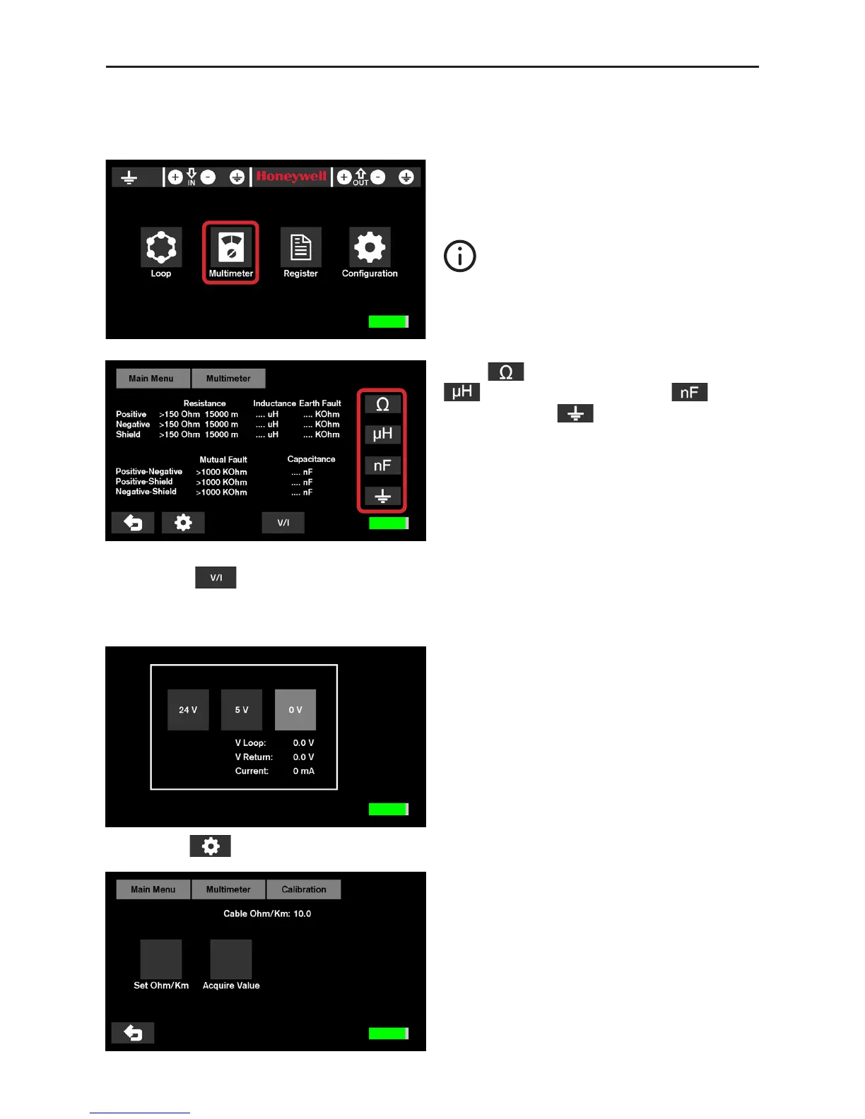
Press to display the resistance values,
for the inductance values, for the
capacity values, for the ground values.
Please see Fire panel specification require-
ments for recommended values.
Then check for each voltage range (0V, 5V and 24V) the voltages and consumption shown by
pressing key .
Check for possible drifts, short circuits, faulty elements, connections or inadequate system de-
vices or external to the system depending on the values obtained.
The 24V reading will provide a reference voltage
drop in the loop, a V return below 17Vdc in-
dicates that the resistance is too high in the
loop.
Below the 5V reading there should not be
consumption. Check the possible existence of
junctions or inductions.
“Set Ohm/Km” allows the direct setting of the
values through the numeric keypad.
Ohm/Km may be changed depending on the
cable used.
“Acquire Value” allows measuring the
resistance value after inserting the cable
length.
After the connection check that POL
200TS has the correct load level.
Please note that batteries with an in-
sufficient charge level can falsify the
measurements.
By pressing the resistance value of connectors (Ohm/Km) can be set.
 Loading...