EasyManua.ls Logo

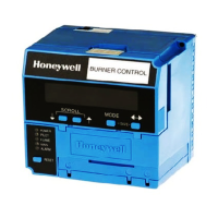
Honeywell RM7898A1000 User Manual

Honeywell RM7898A1000
32 pages
To Next Page IconTo Next Page
Page #1 background image
INSTALLATION INSTRUCTIONS
32-00209-03
SIL
3
Capable
RM7898A
7800 SERIES Valve Proving
Primary Relay Modules
APPLICATION
The RM7898 is a microprocessor-based integrated burner
control for automatically fired gas, oil or combination fuel
single burner applications. The RM7898 system consist of a
relay module, subbase, amplifier, and purge card. Options
include Keyboard Display Module (KDM), Personal Computer
Interface, Data ControlBus™ Module, remote display
mounting, Expanded Annunciator and Combustion System
Manager® Software.
Functions provided by the RM7898 include automatic
burner sequencing, flame supervision, system status
indication, system or self-diagnostics and
troubleshooting.
This document covers the following 7800 Series Relay
Modules:
RM7898A1000
RM7898A1018
RM7898A2000
RM7898A2018
The RM7898 provides unique functions to a standard
primary control.
As received, the RM7898 offers the following features:
Interrupted pilot with 10 second pilot flame establishing
period.
Main valve operation with 10 second MFEP.
Pre-Ignition Interlock (POC) input.
Shutter-driven output when appropriate amplifier is
selected (R7861A, R7886A, R7851C).
Blinking Fault Code Power LED on safety shutdown.
RM7898A1018 offers early spark shutoff when flame is
sensed.
Available features when appropriate terminals are
energized:
Intermittent pilot T8 (Terminal 19).
Direct spark feature for Valve Proving System (VPS)
(Terminal 18).
Valve Proving System function (Terminal 17).
See “Appendix b - ignition options” on page 25 for
examples of 24 single or dual fuel system combinations
with or without using the Valve Proving feature.
Programmable features using the S7800A1142 Keyboard
Display Module (KDM) (not included):
Postpurge time—(up to 60 minutes).
Valve Prove System features, including:
—VPS test time
When in burner sequence to conduct VPS time
(Never, Before, After, Both or Split):
NOTE: The S7800A1142 Series 5 or higher can be pro-
grammed for ModBus Communication. (See 65-0288
Spec Sheet.)
At commissioning time, the Valve Proving System may be
scheduled to occur at one of five different times:
1. Never—Device default as received; valve proving
does not occur. (Demand wired to Terminal 6.)
2. Before—Valve proving after standby and safe start
check, prior to ignition trials, concurrent with Pre-
Purge.
3. After—Valve proving occurs after the Run state
before the device goes to Standby, concurrent with
postpurge.
4. Both—Valve proving occurs at both times Before and
After noted above.
5.
Split—The Main Valve 2 (MV2) (high pressure) seat test
is performed at the Before time and the Main Valve 1
(MV1) (low pressure) seat test is performed during the
After time.
To perform Valve Proving, it must be commissioned and
Demand Input (Terminal 17) must be used.
The following assumptions apply when using the RM7898
Valve Proving testing.
Fig. 1. Valve Proving System—simplified diagram.
MV1
MV2
VP
SW.
M24161
OUTLET
INLET
1
CAUTION: VALVE ENERGIZING TIMING IS BASED ON HONEYWELL VALVE
OPENING TIMES OF 13 SECONDS MAXIMUM.
− FOR VALVES WITH TIMINGS GREATER THAN 13
SECONDS OR THOSE THAT DO NOT OPEN THE ACTIVE
VALVE WITHIN THE ENERGIZED TIME, A BYPASS
SOLENOID VALVE (1/4”, 120 VAC) IS REQUIRED TO
OBTAIN THE PROPER TEST PRESSURES.
− THE BYPASS VALVE WILL BE WIRED IN PARALLEL TO THE
VALVE IT IS BYPASSING (TERMINAL 9 FOR MV1 OR
TERMINAL 21 FOR MV2).
1

Questions and Answers:

Honeywell RM7898A1000 Specifications

General IconGeneral
Frequency50/60 Hz
ApplicationIndustrial and commercial burners
Operating Temperature-40°C to 70°C
ApprovalsUL, CSA, CE
MountingPanel Mount
Relay Outputs2
Weight0.5kg

Summary

APPLICATION

INSTALLATION INSTRUCTIONS

SPECIFICATIONS

Electrical Ratings

Details voltage, frequency, power dissipation, and total connected load ratings for the RM7898.

INSTALLATION

Product Installation Guidance

Provides critical steps and warnings to follow before and during product installation.

VALVE PROVING TEST OPTIONS

WIRING SUBBASE AND SEQUENCE CHART (WITH VALVE PROVING)

FINAL WIRING CHECK

TERMINAL RATINGS AND COMBINATIONS

RM7898 Terminal Specifications

Lists the voltage, current, and pilot duty ratings for each terminal on the RM7898.

STATIC CHECKOUT PROCEDURE

Pre-Installation Checkout Steps

Explains performing checkout on the subbase before installing the relay module.

Safety Precautions During Testing

Highlights warnings for fire/explosion hazards and electrical hazards during testing.

STATIC CHECKOUT TESTS

Test 1: Line Voltage at Terminal 5

Verifies line voltage presence at terminal 5 as part of the checkout procedure.

Test 3: Burner Motor Operation Verification

Checks burner motor start and line voltage at terminal 7 within 10 seconds.

Test 6: Ignition and Pilot Valve Operation

Verifies ignition spark and automatic pilot valve operation.

VALVE PROVING SYSTEM EXPLANATION

Purpose and Leak Detection

Explains the system's goal to test valve seat integrity and detect leaks.

Valve Proving Schedule Options Overview

Details the five scheduling options for the Valve Proving system: Never, Before, After, Both, Split.

VALVE PROVING SYSTEM DETAILS

Split Test Procedure Description

Explains how upstream and downstream seat tests are performed in the Split option.

Pressure Switches for VPS Selection

Identifies the need for and recommends specific Honeywell pressure switches for Valve Proving.

SETUP OF VALVE PROVING FUNCTION

Standby/Setup Screen Navigation Guide

Guides users on navigating to the Setup screen from the Standby state.

Password Entry for Setup Access

Details the procedure for entering the password to access the setup menu.

Setting Valve Proving Test Time Procedure

Instructs on how to set the duration for the Valve Proving test via the KDM.

SETUP CONFIRMATION AND POSTPURGE CONFIGURATION

Saving Valve Proving Setup Changes Method

Explains how to save the configured Valve Proving settings.

Setting Post Purge Time Procedure

Guides on configuring the Post Purge time using the KDM interface.

FINALIZING SETUP AND MODULE MOUNTING

PRINCIPAL TECHNICAL FEATURES

Safety Shutdown (Lockout) Conditions List

Lists all conditions that will cause the RM7898 to enter a safety shutdown (lockout) state.

OPERATION SEQUENCE OVERVIEW

PRE-PURGE AND IGNITION TRIALS

CONFIGURABLE JUMPER OPTIONS

TROUBLESHOOTING GUIDE

Understanding Blink Fault Codes

Explains how blink codes identify faults and how to interpret them.

Code 1-1: Low AC Line Voltage Fault

Describes a low AC line voltage fault and recommended troubleshooting steps.

Code 2-1: Unexpected Flame Signal Fault

Details faults related to unexpected flame signals during standby or purge.

CONTINUED BLINKING FAULT CODE TROUBLESHOOTING

Code 2-2: Flame Signal Absent Fault

Troubleshooting for no flame signal at the end of PFEP or during RUN.

Code 3-3: VPS in Improper State Fault

Troubleshooting for the Valve Proving Switch being in the wrong state during a VPS test.

FURTHER FAULT CODE TROUBLESHOOTING

Code 4-3: Flame Amplifier Problem Fault

Troubleshooting steps for issues with the flame amplifier or detector.

APPENDIX A: VALVE PROVING TEST PROCEDURE

Valve Proving Test Purpose and Leak Detection

Explains the system's goal to test valve seat integrity and detect leaks.

Calculating Valve Train Volume Formula

Provides the formula to calculate the volume between the two valves for testing.

Calculating Valve Proving Test Time Formula

Provides the formula to calculate the minimum test time based on pressure and volume.

VPS WORKSHEET EXAMPLE AND TABLES

Example Calculation of Valve Proving Test Time

Shows an example calculation for the Valve Proving test time.

APPENDIX B - IGNITION OPTIONS

CONTINUED IGNITION OPTIONS

VALVE PROVING DUAL FUEL WIRING DIAGRAMS

MORE VALVE PROVING DUAL FUEL WIRING DIAGRAMS

SAFETY AND SECURITY FEATURES

Physical Device Protection Recommendations

Recommendations for securing the device physically and preventing unauthorized access.

Related product manuals