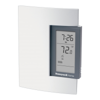
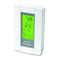
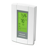
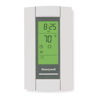
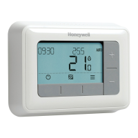
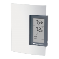
TL8100 PROGRAMMABLE THERMOSTAT
3 69-2017EFS—01
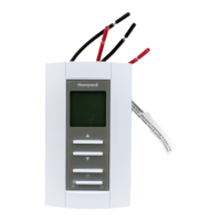
Fig. 11. Wiring for a home automation system.
4. THERMOSTAT
CONFIGURATION
Table 1 shows the configuration of the switches on the back of
the front module. Default settings are inside the shaded cells.
Temperature Control Mode
Choose proportional adaptive mode by placing switch #5 in
the up position for these types of systems.
• Hot water heat systems
• Gas, oil, or electric furnaces
• Electric radiant or convection heating
See Table 2 to set switches #1 and #2 for how to configure
proportional adaptive mode.
Choose conventional mode by placing switch #5 in the down
position for these types of systems:
• Gas or oil furnace or boiler with a 30-second or longer
combustion gas prepurge cycle. To figure out the gas
purging cycle of your system, measure the time lapse from
the instant the thermostat sends the heating command to
the instant the burner actually goes on.
• Systems where the user desires to set how many degrees
the air temperature must fall before the thermostat calls for
heat. In general, the slower the HVAC system is able to
distribute heat, the smaller the the differential should be.
• When more than one TL8100 is wired directly to one zone
valve or one zone circulator.
See Table 3 to set switches #1 and #2 for how to configure
conventional mode.
Table 1.
Switches Description Up Down
1 & 2
Cycle length
(proportional)
Deadband
(conventional)
See Table 2 and 3.
3 Clock display
12H 24H
4
Temperature
display
a
a
Every time you change the temperature display format, the
comfort and economy preset temperatures return to their
default settings.
°F °C
5
Temperature
control mode
Proportional
Mode
(see “Tempera-
ture Control
Mode”)
Conventional
Mode
(see “Tempera-
ture Control
Mode”)
6
Pump protection
b
b
For hot water installations, it is recommended to enable
this function to activate the pump for one minute every 24
hours to prevent pump seizure.
Deactivate Activate
TL8100 HOME AUTOMATION
SYSTEM
12 VDC
± 10%
M29972
Table 2. Proportional Mode.
Cycle
length Heating Type Position
5 minutes
(12 CPH)
For faster cycling systems
10 minutes
(6 CPH)
Fossil fuel or electric wall furnaces, elec-
tric forced air, electric radiant or convec-
tion heating
15 minutes
(4 CPH)
Standard efficiency fossil fuel forced air
systems or high temperature, fast
response, hot water systems
20 minutes
(3 CPH)
High efficiency fossil fuel systems or slow
response hot water systems
Table 3. Conventional Mode.
Differential Position
0.5 °F (0.3 °C)
0.7 °F (0.4 °C)
0.9 °F (0.5 °C)
1.1 °F (0.6 °C)
 Loading...