VPI PRESSURE INDEPENDENT CONTROL VALVES & ACTUATORS
9 31-00383-01
Installation of Actuators compatible with DN 15-50
IMPORTANT: Do not connect power to the actuator unless the actuator is already fitted on the valve and NEVER
install the actuator in a closed position this may damage the valve.
IMPORTANT: The actuator is supplied in an open position to ensure the easy commissioning of the system.
Procedure to install the Actuator
The procedure to install the actuator is as follow:
1. Install the valve body.
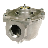
2. Mount the actuator on the valve as per the directions shown below.
Figure 12. Assembly direction of an actuator on valve (example)
3. Tighten the connection union as shown below. Do not use additional tools as it may damage the actuator.
Mounting Position
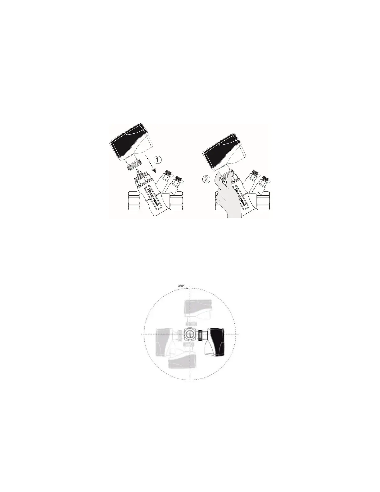
The actuators can be mounted in any position (IP54 is dependent upon orientation; see Figure 13). Choose a mounting
position permitting easy access to cables and controls. To guarantee IP54, upside-down installation is only
recommended.
Figure 13. Actuator mounting for IP54
Procedure to remove the Actuator
1. Electrically open the actuator by activating DIP switch #6 for easier removal.
2. Hereafter finger loosen the connection union. Do not use additional tools as it may damage the actuator.
IMPORTANT: Please make sure that the actuator is electrically opened, before re-fitting it on the valve.
 Loading...