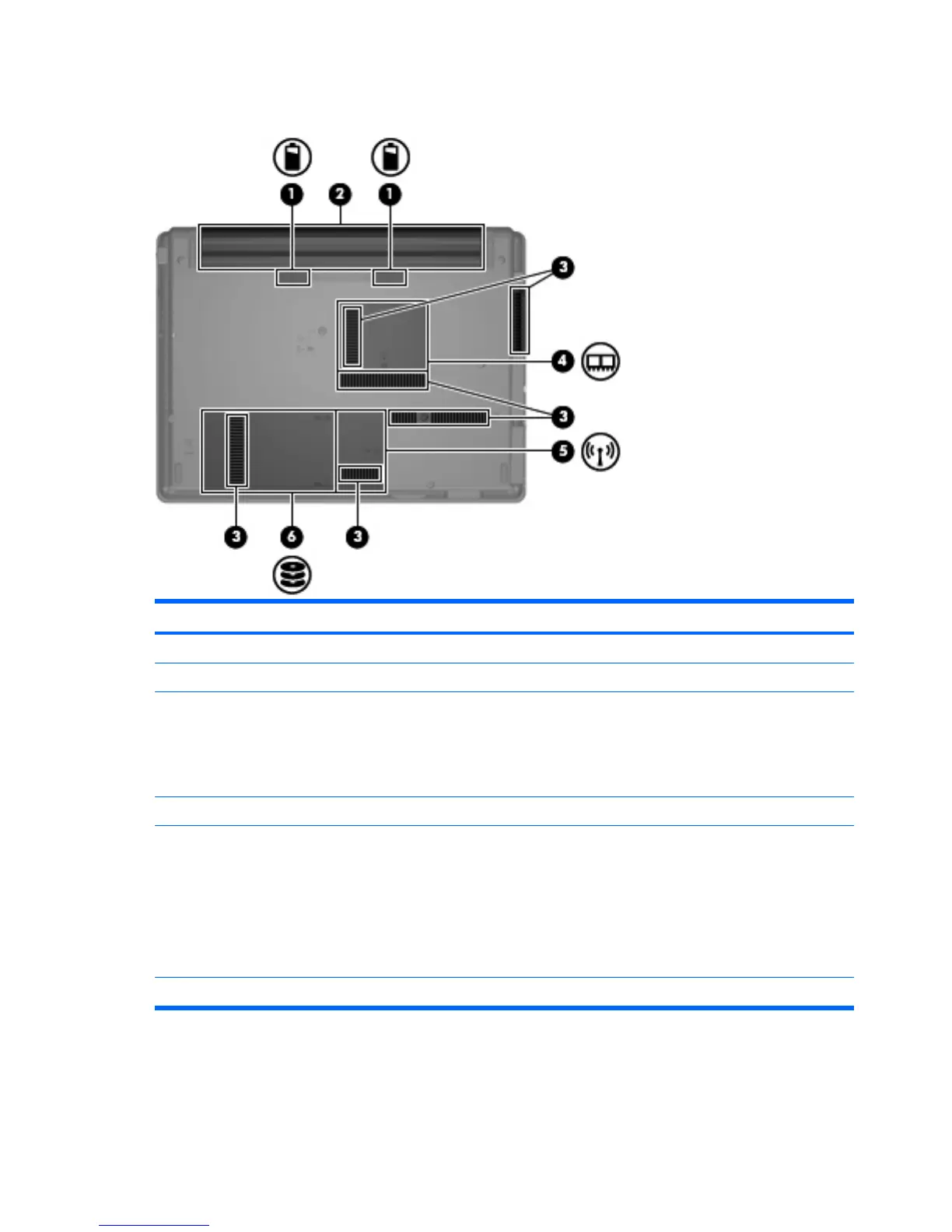
Bottom components
Item Component Function
(1) Battery release latches (2) Release the battery from the battery bay.
(2) Battery bay Holds the battery.
(3) Vents (6) Enable airflow to cool internal components.
NOTE: The computer fan starts up automatically to cool
internal components and prevent overheating. It is normal
for the internal fan to cycle on and off during routine
operation.
(4) Memory module compartment Contains the memory module slots.
(5) WLAN module compartment (select models only) Contains a WLAN module slot.
NOTE: To prevent an unresponsive system, replace the
wireless module only with a wireless module authorized for
use in the computer by the governmental agency that
regulates wireless devices in your country or region. If you
replace the module and then receive a warning message,
remove the module to restore computer functionality, and
then contact technical support through Help and Support.
(6) Hard drive bay Holds the hard drive.
12 Chapter 2 External component identification
 Loading...