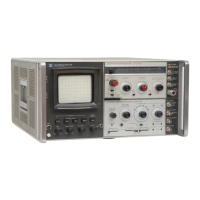
Model8555A
Installation
SECTION
II
INSTAllATION
2-1. INITIAL INSPECTION
2-2. Mechanical Check
2-3.
Check
the
shipping
carton
for
evidence
of
damage
immediately
after
receipt.
If
there
is
any
visible damage
to
the
carton,
request
the
carrier's
agent be
present
when
the
instrument
is
unpacked.
Inspect
the
instrument
for
physical damage such as
bent
or
broken
parts
and
dents
or
scratches.
If
damage is
found
refer
to
paragraph 2-6
for
recom-
mended
elaim
procedures.
If
the
instrument
appears
to
be
undamaged,
perform
the
electrical
check (see paragraph 2-4).
The
packaging material
should be
retained
for
possible
future
use.
2-4. Electrical Check
2-5.
The
electrical
check
consists
of
following
the
performance
test
procedures
listed in Section IV.
These procedures allow
the
operator
to
determine
that
the
instrument
is,
or
is
not,
operating
within
the
specificaions listed in Table 1-1.
The
initial per-
formance
and
accuracy
of
the
instrument
are certi-
fied as
stated
on
the
inside
front
cover
of
this
manual.
If
the
instrument
does
not
operate
as
specified, refer
to
paragraph
2-6 for
the
recom-
mended
claim
procedure.
2-6. CLAIMS
FOR
DAMAGE
2-7. If physical damage is
found
when
the
instru-
ment
is
unpacked,
notify
the
carrier
and
the
near-
est Hewlett-Packard Sales/Service office immedi-
ately.
The
Sales/Service office will arrange
for
repair
or
replacement
without
waiting
for
a claim
to
be
settled
with
the
carrier.
2-8.
The
warranty
statement
for
the
instrument
is
on
the
inside
front
cover
of
this manual.
Contact
the
nearest Sales/Service office
for
information
about
warranty
claims.
2-9.
PREPARATION
FOR
USE
~~~:~~§]
Before applying power,
check
the
rear
panel slide switch
on
the
Display
Section
for
proper
posi-
tion
(115
or
230
volts).
2-10. Shipping
Configuration
2-11.
Because
of
individual
customer
require-
ments,
shipping
configurations
are flexible.
Preparation
for
use is based
on
the
premise
that
the
RF
and
IF
Sections are installed in a Display
Section
to
make
the
Spectrum
Analyzer
physically
and
functionally
complete
for
use. Since
the
RF
and
IF
Sections
are usually received
separately,
the
plug-ins
must
be
mechanically
fitted
together,
elec-
trically
connected,
and
inserted in a
display
section
or
oscilloscope mainframe
of
the
140-series.
For
mechanical
and
electrical
connections,
refer
to
Figure 2-1
and
paragraph 2-20.
2-12.
Power
Requirements
2-13.
The
Spectrum
Analyzer can
be
operated
from
a 50-
to
60-hertz
input
line
that
supplies
either
a
115-volt
or
230-volt (±10% in
each
case)
power.
Consumed
power
varies
with
the
plug-ins
used
but
is
normally less
than
225
watts.
Line
power
enters
the
Display
Section
or
Mainframe,
where
it
is converted
to
de
voltages,
and
then
is
distributed
to
the
RF
and
IF
Sections
via
internal
connectors.
2-14.
The
115/230
power
selector
switch
at
the
rear
of
Display Section
must
be
set
to
agree
with
the
available line voltage. If
the
line
voltage
is
115
volts,
the
slide switch
must
be
positioned
so
that
115
is
clearly visible.
The
instrument
is
internally
fused
for
115-volt
operation,
when
shipped.
If
230-volt
source
is
to
be used,
refer
to
fuse replace-
ment
procedures
in
the
display
section
manuaL
2-15.
Power
Cable
2-16.
To
protect
operating
personnel,
the
National
Electrical Manufacturers Association
(NEMA)
and
the
International
Electrotechnical
Commission
(IEC)
recommends
that
the
instrument
panel
and
cabinet
be
grounded.
The
Spectrum
Analyzer
is
equipped
with
a
three-conductor
power
cable;
the
third
conductor
is
the
ground
conductor
and
when
the
cable is plugged
into
an
appropriate
receptacle,
the
instrument
is
grounded.
To
preserve
the
protec-
tion
feature
when
operating
the
instrument
from
a
two-contact
outlet,
use a
three-prong
to
two-prong
adapter
and
connect
the
green lead
on
the
adapter
to
ground.
2-17.
Operating
Environment
2-18.
The
Spectrum
Analyzer uses a forced-air
cooling
system
to
maintain
required
operating
tem-
peratures
within the
instrument.
The
air
intake
and
filter
are
located
on
the
rear
of
the
Display Sec-
2-1

 Loading...