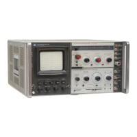
Modei8555A
as little as 2 kHz/div,
or
the
scanning capabilities
can
be
eliminated
altogether
to
use
the
instrument
as a fixed-tuned receiver. A
300kHz
IF
bandwidth
is automatically selected
for
full-scan operation;
for variable-scan and fixed
frequency
operation,
bandwidths
as narrow as
100Hz
can
be
selected. A
single switch will
automatically
enable
the
first LO
tuning
stabilization circuit
when
scan
widths
of
100
kHz
per
division,
or
less, are selected. A signal
identifier circuit,
controlled
by
an
on/off
switch,
allows
the
operator
to
quickly
determine
the
har-
monic mixing
mode
and
select
the
appropriate
frequency
band.
The signal identifier can be
enabled for
scan
widths
of
1 MHz
per
division
or
less.
1-19. OPTIONS
1-20.
Option
001.
Replaces
type
N
with
type
AP.C-7
connector.
1-21.
Option
002
for
the
Model
8555A
is a limiter
which can
be
installed
between
the
RF
Section's
INPUT
port
and
the
input
attenuator
to
protect
input
circuitry
from
being
overdriven. See
Appendix A
for
details regarding
Option
002.
1-22. ACCESSORIES SUPPLIED
1-23. The
RF
Section is
shipped
with
three
coaxial
type
terminations and
one
multi-section termina-
tion.
The coaxial
terminations
are installed
on
the
EXT
MIXER
port,
the
FIRST
LO OUTPUT
port
and
the
SECOND LO
OUTPUT
port.
(See Figure
3-1, items
17,
18,
and
19.)
The
multi-section
termination is shipped
taped
to
the
top
of
the
RF
Section. Install
the
multi-section
termination
on
the
Display Section rear panel. (See
item
3, Figure
3-3.)
The
coaxial
terminations
are HP
part
number
11593A
and
the
multi-section
termination
is
HP
part
number
08553-60122.
General
Information
1-24. EQUIPMENT REQUIRED BUT NOT
SUPPLIED
1-25.
The
8555A
Spectrum
Analyzer
RF
Section
must
be
mated
with
an 8552-series
Spectrum
Analyzer
IF
Section and
one
of
the
140-series
Display
Sections
or
140-series Oscilloscope Main-
frames
before
the
units can
perform
their
function
as a
spectrum
analyzer.
The
140S/140T/143S
Dis-
play
Sections
are
equipped
with
a fixed -persis-
tence/non-storage
CRT, whereas
the
141S
and
141
T Display Sections are
equipped
with
a
variable-persistence storage
CRT. Overlays,
to
provide
LOG and LINEAR graticule scales, are
available
for
use
with
the
standard
140A
and
141A
Oscilloscope Mainframe.
1-26.
Operating
accessories
for
use
with
the
8555/8552/140
Spectrum
Analyzer
are
listed
in
Table
1-3. Operating accessories
include
a wave-
guide
mixer,
adapters, filters
and
a
frequency
comb
generator.
An
external
waveguide
mixer
and
appropriate
adapters
are
required
over
the
fre-
quency
range
of
18
to
40
GHz.
1-27.
WARRANTY
1-28.
The
8555A
Spectrum
Analyzer
RF
Section
is
warranted
and certified
as
indicated
on
the
inner
front
cover
of
this manual.
For
further
information
contact
the
nearest Hewlett-Packard Sales
and
Service Office; addresses are provided
at
the
back
of
this
manual.
1-29. RECOMMENDED TEST EQUIPMENT
1-3 0. Tables 1-4
and
1-5 list
the
test
equipment
and
test
equipment
accessories
required
to
check,
adjust,
and
repair
the
8555A
Spectrum
Analyzer
RF
Section.
1-3

 Loading...