Model8555A
Operation
SECTION
Ill
OPERATION
3-1. INTRODUCTION
3-2.
This section provides
complete
operation
in-
structions
for
the
HP
8555A/8552A/140-series
Spectrum
Analyzer.
Front
panel
controls,
connec-
tors
and
indicators, for
the
8555A
RF
Section,
are
identified
and
described in
Figure
3-1.
Controls
and
indicators,
for
a
typical
Display
Section
and
IF
Section, are
identified
and
described
in
Figure
3-2.
Refer
to
the
appropriate
IF
Section
and
Dis-
play
Section
manuals
for
identification
and
description
of
controls,
indicators,
and
connectors
not
contained
in this manual.
Operational
adjust-
ments
are detailed in Figure 3-3
and
general opera-
ting
instructions
are
provided
in Figures 3-4
through
3-6.
3-3.
PANEL FEATURES
3-4.
Front
panel features
of
the
8555A
RF
Sec-
tion
are described in Figure 3-1.
Front
and
rear
panel views
of
the
HP
8555A/8552A/140T
Spec-
trum
Analyzer are
shown
in Figure 3-3.
For
a
detailed description
of
the
IF
Section
and
Display
Section
controls
and
indicators,
refer
to
the
opera-
tion
and
service manuals
for
those
instruments.
Interconnection
wiring
between
the
RF
Section
and
the
IF
Section
and
between
the
RF
Section
and
the
Display Section is
contained
in
Section
VIII
of
this manual.
3-5. OPERATOR'S CHECKS
3-6.
Upon
receipt
of
the
instrument,
or
when
one
or
more sections
of
the
analyzer
are changed, per-
form
the
operational
adjustment
procedures
listed
in
Figure 3-3. This
procedure
corrects
for
minor
differences
between
units
and
ensures
that
the
RF
Section,
IF
Section
and
Display Section are
properly
matched.
3-7. OPERATING INSTRUCTIONS
3-8.
General operating
instructions
are
contained
in Figure 3-4. These
instructions
will familiarize
the
operator
with
basic
operating
functions
of
the
spectrum
analyzer.
Additional
information
cover-
ing
signal identifying
techniques
and
external
mixer
operation
is
contained
in Figures 3-5
and
3-6.
3-9. CONTROLS, INDICATORS
AND
CONNECTORS
3-10.
Front
panel controls,
indicators,
and
connec-
tors
are
identified
and
briefly
described
in Figures
3-1
and
3-2.
Operational
Adjustment
procedures
are given in Figure 3-3. Additional
information,
to
assist
the
user
during
instrument
operation,
is
given in
the
following paragraphs.
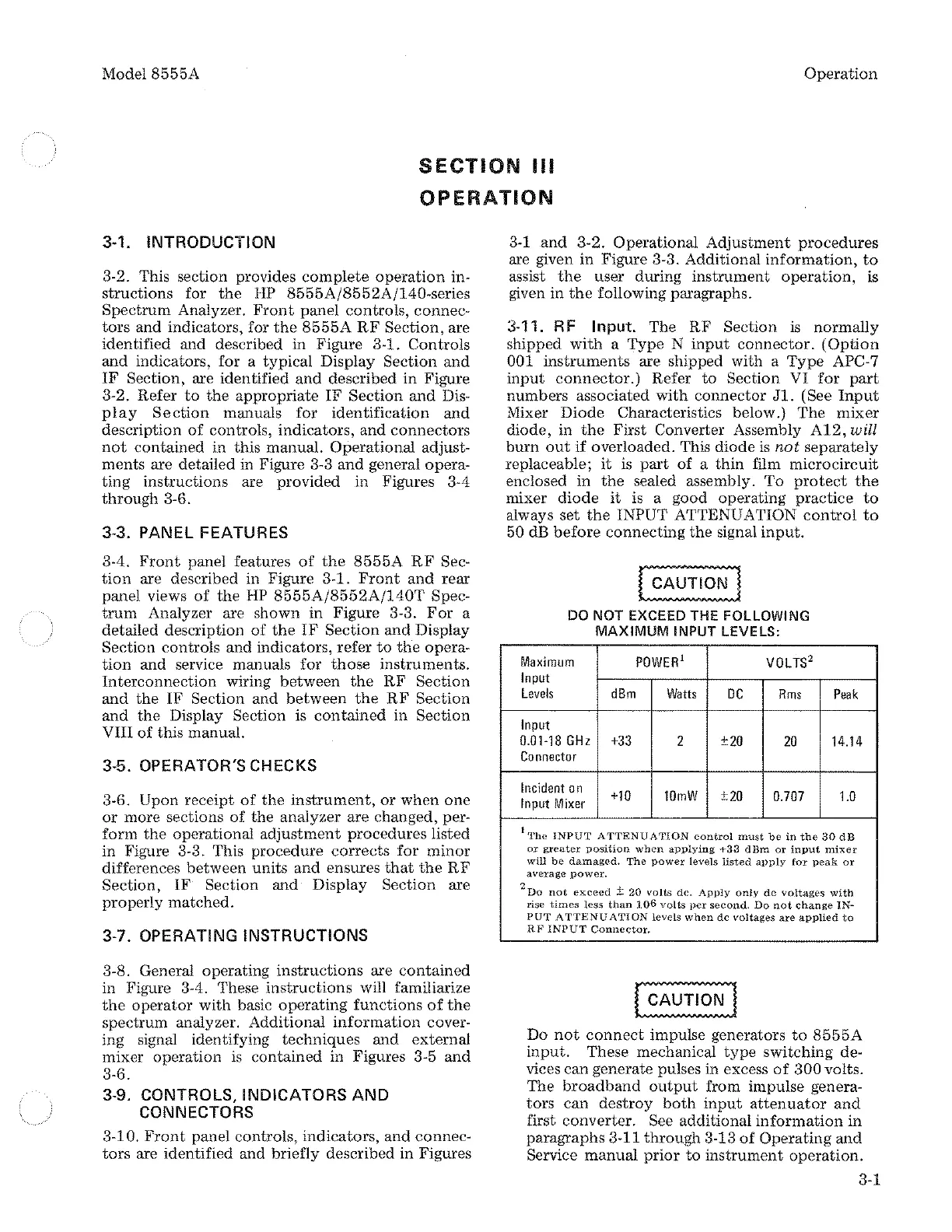
3-11. RF Input.
The
RF
Section
is
normally
shipped
with
a
Type
N
input
connector.
(Option
001
instruments
are shipped
with
a
Type
APC-7
input
connector.)
Refer
to
Section
VI
for
part
numbers
associated
with
connector
Jl.
(See
Input
Mixer
Diode
Characteristics below.)
The
mixer
diode,
in
the
First
Converter Assembly
A12,
will
burn
out
if
overloaded.
This
diode
is
not
separately
replaceable;
it
is
part
of
a
thin
film
microcircuit
enclosed
in
the
sealed assembly.
To
protect
the
mixer
diode
it
is a good
operating
practice
to
always
set
the
INPUT ATTENUATION
control
to
50 dB
before
connecting
the
signal
input.
DO NOT EXCEED THE FOLLOWING
MAXIMUM
INPUT LEVELS:
Maximum
POWER
1
VOLTS
2
Input
Levels
dBm
Watts
DC
Rms
Input
Peak
0.01-18
GHz
+33
2
±20
20
14.14
Connector
Incident
on
+10
10mW
±20
0.707
1.0
Input
Mixer
l
The
INPUT
ATTENUATION
control
must
be
in
the
.30
dB
or
greater
position
when
applying
+33
dBm
or
input
mixer
will
be
damaged.
The
power
levels
listed
apply
for
peak
or
average
power.
2
Do
not
exceed±
20
volts
de.
Apply
only
de
voltages
with
rise
times
less
than
106
volts
per
second.
Do
not
change
IN-
PUT
A'rTENUATION
levels
when
de
voltages
are
applied
to
RF
INPUT
Connector.
Do
not
connect
impulse generators
to
8555A
input.
These mechanical
type
switching
de-
vices
can
generate
pulses in excess
of
300
volts.
The
broadband
output
from impulse genera·
tors
can
destroy
both
input
attenuator
and
first
converter.
See
additional
information
in
paragraphs
3-11
through
3-13
of
Operating
and
Service
manual
prior
to
instrument
operation.
3-1

 Loading...


