General
Information
Mode!8555A
Table 1-1.
8555A/8552A/8552B
Specifications
1-4
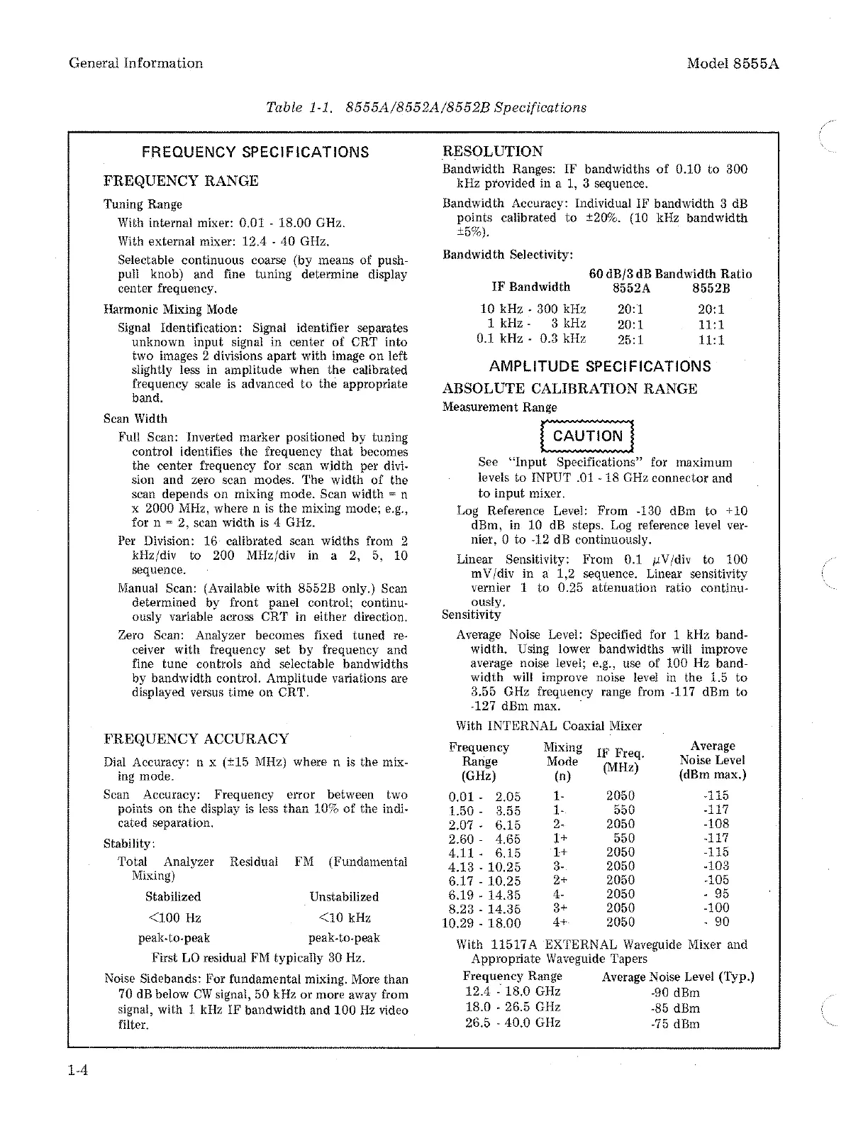
FREQUENCY SPECIFICATIONS
FREQUENCY RANGE
Tuning Range
With internal mixer: 0.01 - 18.00 GHz.
With external mixer: 12.4 -
40
GHz.
Selectable continuous coarse (by means
of
push-
pull knob) and fine tuning determine display
center frequency.
Harmonic Mixing Mode
Signal Identification: Signal identifier separates
unknown input signal in center
of
CRT into
two images 2 divisions apart with image
on
left
slightly less in amplitude when the calibrated
frequency scale
is
advanced
to
the appropriate
band.
Scan Width
Full Scan: Inverted marker positioned
by
tuning
control identifies the frequency
that
becomes
the center frequency for scan width per
divi-
sion and zero scan modes. The width
of
the
scan depends on mixing mode.
Scan width = n
x
2000 MHz, where n is the mixing mode; e.g.,
for n = 2, scan width is 4 GHz.
Per Division: 16 calibrated scan widths from 2
kHz/div to
200 MHz/div in a 2, 5, 10
sequence.
Manual
Scan: (Available with 8552B only.) Scan
determined by front panel control; continu-
ously variable across
CRT
in either direction.
Zero Scan: Analyzer becomes fixed tuned
re-
ceiver with frequency set
by
frequency and
fine tune controls and selectable bandwidths
by bandwidth control. Amplitude variations are
displayed versus time on
CRT.
FREQUENCY ACCURACY
Dial
Accuracy: n x (±15 MHz) where n
is
the mix-
ing mode.
Scan Accuracy: Frequency
error
between two
points on
the
display is less than 10%
of
the indi-
cated separation.
Stability:
Total Analyzer Residual FM (Fundamental
Mixing)
Stabilized
<100Hz
peak-to-peak
Unstabilized
<10kHz
peak-to-peak
First
LO
residual FM typically 30 Hz.
Noise Sidebands: For fundamental mixing. More than
70 dB below
CW
signal, 50 kHz or more away from
signal, with 1 kHz
IF
bandwidth and
100Hz
video
filter.
RESOLUTION
Bandwidth Ranges: IF bandwidths
of
0.10
to
300
kHz provided in a 1, 3 sequence.
Bandwidth Accuracy: Individual IF bandwidth 3 dB
points calibrated
to
±20%. (10 kHz
bandwidth
±5%).
Bandwidth Selectivity:
60 dB/3 dB Bandwidth
Ratio
IF
Bandwidth 8552A 8552B
10
kHz - 300 kHz
1kHz-
3kHz
0.1 kHz - 0.3 kHz
20:1
20:1
25:1
20:1
11:1
11:1
AMPLITUDE SPECIFICATIONS
ABSOLUTE CALIBRATION RANGE
Measurement
Rang:e
,_[~~-~~ii:O"""""'i~~J
See
"Input
Specifications" for maximum
levels
to
INPUT .01 - 18 GHz connector and
to
input
mixer.
Log Reference Level: From
-130 dBm
to
+ 10
dBm, in 10 dB steps. Log reference level ver-
nier, 0 to -12 dB continuously.
Linear Sensitivity: From
0.1
11V/div
to
100
mV/div in a 1,2 sequence. Linear sensitivity
vernier 1
to
0.25 attenuation ratio continu-
ously.
Sensitivity
Average Noise Level:
Specified for 1 kHz band-
width. Using lower bandwidths will improve
average noise level; e.g., use of
100 Hz band-
width will improve noise level
in
the 1.5
to
3.55 GHz frequency range from -117 dBm
to
-127 dBm max.
With INTERNAL Coaxial Mixer
Frequency Mixing
IF
Freq.
Average
Range
Mode
(MHz)
Noise Level
(GHz)
(n)
(dBm max.)
0.01-
2.05
1- 2050 -115
1.50 -
3.55
1- 550
-117
2.07-
6.15
2-
2050 -108
2.60-
4.65
1+
550
-117
4.11-
6.15
1+
2050 -115
4.13
-
10.25
3- 2050
-103
6.17 -
10.25
2+
2050
-105
6.19 -
14.35
4- 2050 -
95
8.23 -
14.35
3+
2050 -100
10.29 -
18.00
4+
2050 -
90
With
11517
A EXTERNAL Waveguide Mixer and
Appropriate
Waveguide Tapers
Frequency Range Average Noise Level (Typ.)
12.4
- 18.0 GHz
-90
dBm
18.0
- 26.5 GHz
-85
dBm
26.5 40.0 GHz
-75
dBm

 Loading...


