Before removing the Hall sensor board, follow these steps:
1. Shut down the computer. If you are unsure whether the computer is o or in Hibernation, turn
the computer on, and then shut it down through the operating system.
2. Disconnect all external devices connected to the computer.
3. Disconnect the power from the computer by rst unplugging the power cord from the AC outlet and then
unplugging the AC adapter from the computer.
4. Remove the computer feet (see Computer feet on page 23).
5. Remove the keyboard/top cover (see Keyboard/top cover on page 24).
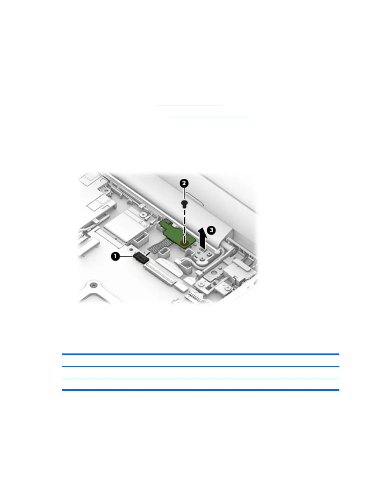
Remove the Hall sensor board:
1. Disconnect the Hall sensor board (1) cable from the system board.
2. Remove the screw holding the Hall sensor board (2) to the base enclosure.
3. Lift the Hall sensor board and cable (3) from the base enclosure.
4. Remove the Hall sensor board.
Reverse this procedure to install the Hall sensor board.
Connector board and cable
Description Spare part number
Connector board (includes SD card reader and SIM slot) 900816-001
Connector board cable 900811-001
Before removing the connector board and cable, follow these steps:
1. Shut down the computer. If you are unsure whether the computer is o or in Hibernation, turn
the computer on, and then shut it down through the operating system.
2. Disconnect all external devices connected to the computer.
Component replacement procedures 29
 Loading...