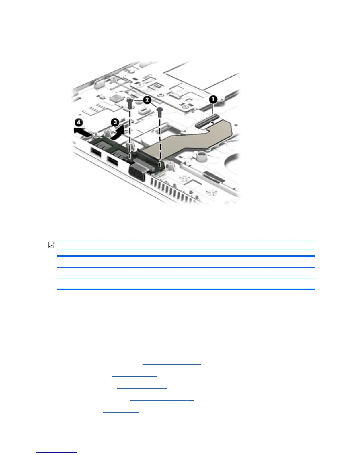
3. Release the USB/VGA connector board (3) from the openings in the base enclosure.
4. Remove the USB/VGA connector board (4) and cable by sliding them away from the heat sink.
Reverse this procedure to install the USB/VGA connector board.
Heat sink
NOTE: The heat sink spare part kit includes replacement thermal material.
Description Spare part number
For use only on computer models equipped with a graphics subsystem with discrete memory 803017-001
For use only on computer models equipped with a graphics subsystem with UMA memory 803016-001
Before removing the heat sink, follow these steps:
1. Turn off the computer. If you are unsure whether the computer is off or in Hibernation, turn
the computer on, and then shut it down through the operating system.
2. Disconnect the power from the computer by unplugging the power cord from the computer.
3. Disconnect all external devices from the computer.
4. Remove the service cover (see Service cover on page 51), and then remove the following components:
a. Battery (see Battery on page 53)
b. Keyboard (see Keyboard on page 63)
c. Base enclosure (see Base enclosure on page 75)
d. Fan (see Fan on page 77)
84 Chapter 6 Removal and replacement procedures for Authorized Service Provider parts ENWW
 Loading...