l The surge protection board cannot be positioned in slot 4 in the BBU to avoid interfering
with power cables in the BTS3900C cabinet.
l The number of surge protection boards (UELP/UFLP/UFLPB) is based on the number of
E1/FE/GE ports that need surge protection in the BBU. The surge protection board is
installed, in descending order of priority, in slot 5, 1, or 0. If slots 5, 1, and 0 are occupied,
the surge protection board can be installed in a vacant slot in the BBU.
l Either the UFLPB or UFLP, but not both of them, can be installed in the surge protection
box. The UFLPB or UFLP is installed in a slot with a higher priority than the UELP.
l The FE/GE fiber optic cables do not need surge protection.
Cable Connections
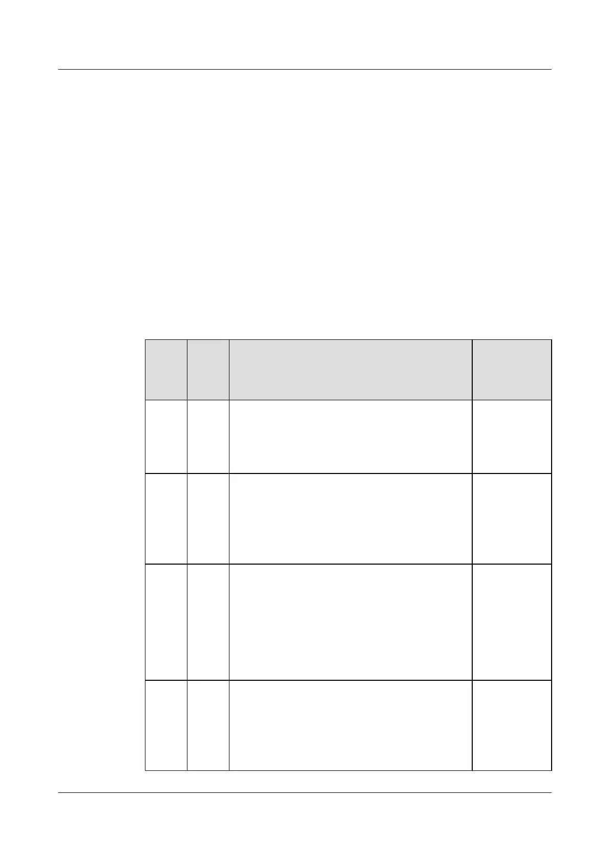
Table 7-16 and Figure 7-8 show cable connections in a dual-mode base station in different
transmission modes.
Table 7-16 Transmission cable connections for a dual-mode base station in independent
transmission mode
Trans
missi
on
Mode
Mode
Supp
orted
Application Scenario Legend
GSM
E1/T1
+UMT
S E1/
T1
GSM
+UMT
S
The transmission cables are connected to the E1/T1
port on the WMPT or UMPT and the GTMU.
"1" in the
Figure 7-8
shows the cable
connections.
GSM
FE/GE
+UMT
S FE/
GE
GSM
+UMT
S
Scenario 1: The transmission cables are connected to
the FE optical port on the WMPT or UMPT and the
GTMU.
Scenario 2: The transmission cables are connected to
the FE electrical port on the WMPT or UMPT and the
GTMU.
"2" in the
Figure 7-8
shows the cable
connections in
scenario 1.
GSM
E1/T1
+LTE
FE/GE
GSM
+LTE
Scenario 1: The UTRP is not configured. The
transmission cables are connected to the E1/T1 port on
the GTMU and the FE optical or electrical port on the
LMPT or UMPT.
Scenario 2: The UTRP is configured on the GSM side.
The transmission cables are connected to the E1/T1
ports on the GTMU and UTRP and to the FE electrical
or optical port on the LMPT or UMPT.
"3" in the
Figure 7-8
shows the cable
connections in
scenario 1.
UMTS
FE/GE
+LTE
FE/GE
GSM
+LTE
Scenario 1: The transmission cables are connected to
the FE electrical port on the LMPT or UMPT and the
GTMU.
Scenario 2: The transmission cables are connected to
the FE optical port on the LMPT or UMPT and FE
electrical port on the GTMU.
"4" in the
Figure 7-8
shows the cable
connections in
scenario 1.
BTS3900C (Ver.C)
Hardware Description 7 BTS3900C Cables
Issue 03 (2013-05-27) Huawei Proprietary and Confidential
Copyright © Huawei Technologies Co., Ltd.
140
 Loading...