Trans
missi
on
Mode
Mode
Supp
orted
Application Scenario Legend
UMTS
E1/T1
+LTE
FE/GE
UMTS
+LTE
Scenario 1: The UTRP is not configured. The
transmission cables are connected to the E1/T1 port on
the WMPT or UMPT and the FE optical or electrical
port on the LMPT or UMPT.
Scenario 2: The UTRP is configured on the UMTS
side. The transmission cable is connected to the E1/T1
port on the UTRP and to the FE electrical or optical
port on the LMPT or UMPT.
"5" in the
Figure 7-8
shows the cable
connections in
scenario 1.
UMTS
FE/GE
+LTE
FE/GE
UMTS
+LTE
Scenario 1: The transmission cables are connected to
the FE electrical port on the LMPT or UMPT and the
WMPT or UMPT.
Scenario 2: The transmission cables are connected to
the FE optical port on the LMPT or UMPT and FE
electrical port on the WMPT or UMPT.
"6" in the
Figure 7-8
shows the cable
connections in
scenario 1.
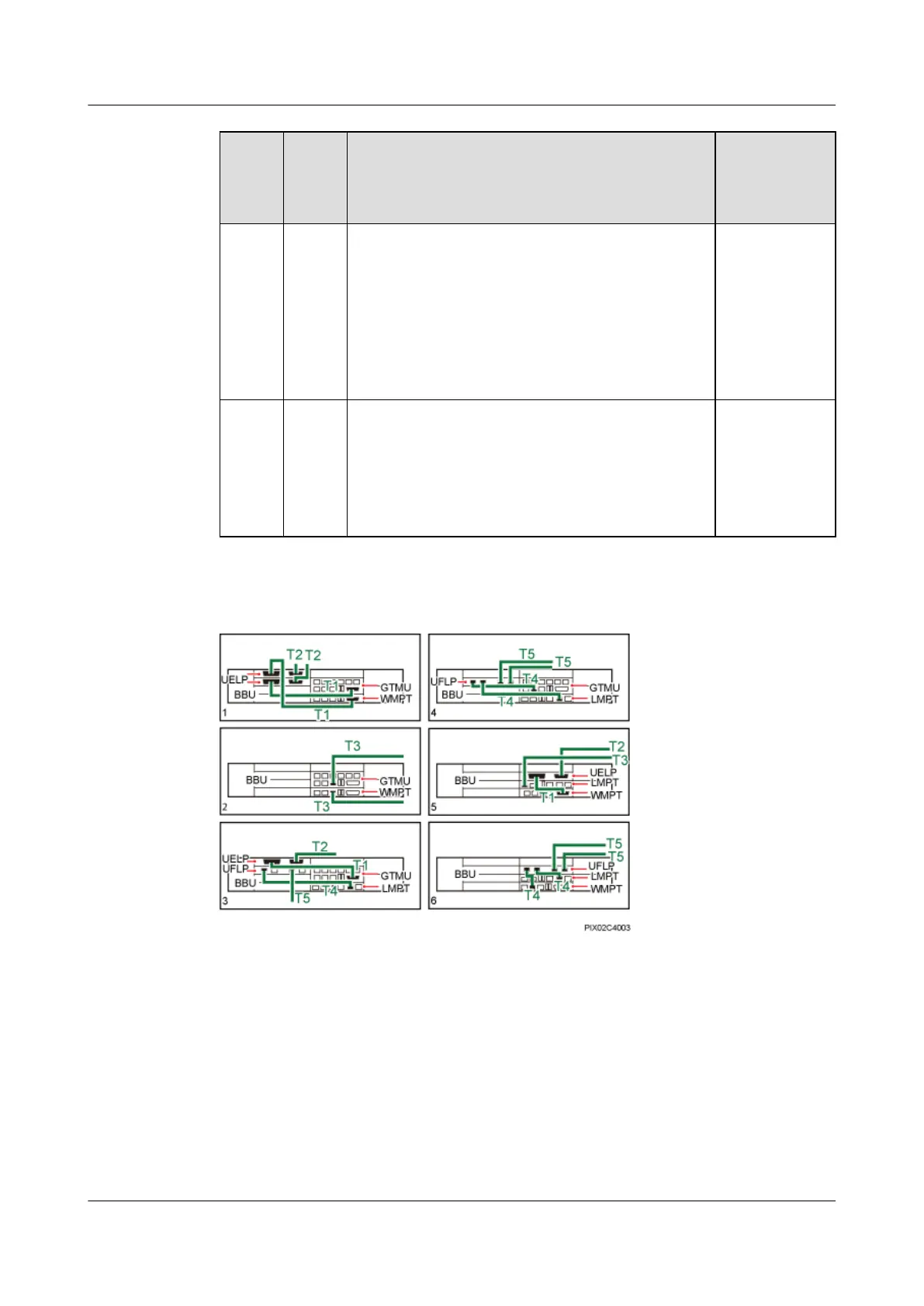
Figure 7-8 Transmission cable connections in a dual-mode base station in separate transmission
mode
T1: E1/T1 Surge Protection
Transfer Cable
T2: 7.6.1 E1/T1 Cable T3: 7.6.7 FE/GE Fiber
Optic Cable
T4: FE Surge Protection
Transfer Cable
T5: 7.6.3 FE/GE Ethernet
Cable
- - -
7.3.3 Monitoring Signal Cable Connections
This section describes the monitoring signal cable connections for a BTS3900C AC cabinet and
a BTS3900C DC cabinet.
BTS3900C (Ver.C)
Hardware Description 7 BTS3900C Cables
Issue 03 (2013-05-27) Huawei Proprietary and Confidential
Copyright © Huawei Technologies Co., Ltd.
141
 Loading...