The new main way is grounded over the ground point on the general input unit.
As shown in Figure 3-76 and Figure 3-77:
1. Each cabinet in the smart module connects to the nearest ground grid using ground
cables with the minimum cross-sectional area of 16 mm
2
.
2. Use 100 x 0.3 copper foils or copper braids with a cross-sectional area of 25 mm
2
for the
equipotential connection grid. Use 30 x 3 copper strips for the equipotential bonding bar
based on the customer's configurations.
Solution 2: S-shaped (Star) Grounding (Not Recommended)
The S-shaped (star) grounding solution is not supported in the scenario where the new main way is
deployed.
⚫
A main ground bar is installed inside the PDC. A branch ground bar is installed inside the
first battery cabinet or IT cabinet adjacent to the PDC. Ground terminals of cabinets
inside the module are connected to the branch ground bar by ground cables with a
minimum cross-sectional area of 16 mm
2
. The main ground bar connects to a floor
earthing bar (FEB) or collective ground bar (copper bar with an area of 25 mm x 3 mm
routed along a cable tray or wall in an equipment room).
⚫
Metal components and parts of cabinets are properly connected. A structural connection
area is protected and applied with antioxidants. A protected area should ensure that two
metal components can be properly connected. The DC resistance is within 0.1 ohm
between any two connected metal components. Use ground cables to connect two metal
components that cannot be directly connected, such as cabinets and cabinet doors. A
cable for connecting these two metal components has a minimum cross-sectional area of
6 mm
2
.
⚫
A ground bar or general ground point is provided in each cabinet for equipment
grounding. These ground bars are not insulated.
⚫
A ground terminal is greater than or equal to M8 in dimensions. A yellow ground label
is attached close to the general ground terminal for cabinets.
Connect equipotential cables to metal components without carrying currents in the module,
such as metal doors and windows, cable trays, and ESD floor supports. Each equipotential
cable has a minimum cross-sectional area of 6 mm
2
.
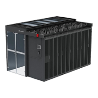
Figure 3-78 shows the equipotential bonding for cabinets in the single-row aisle containment.
 Loading...

