MAINTENANCE
HT4400 Instruction Manual 5-21
3
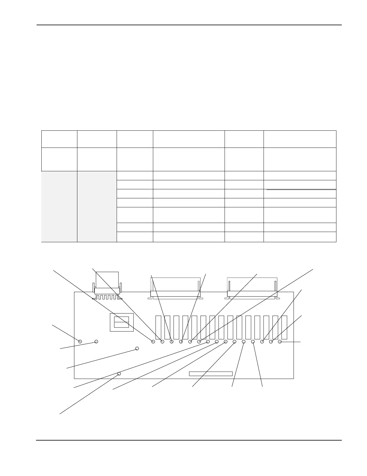
Relay Board PCB4 - Status Indicators
Relay board PCB4 interfaces certain controls in the power supply, ignition console and the valve cluster. The
control board sends a command to the relay board, and the relay board responds by sending 120 VAC to the
control (and also lighting an LED on the relay board). The control board also tells the relay board to shut off the
120 VAC to the particular control (which shuts off the LED). LEDs are located adjacent to the relay that switches
the 120 VAC There are also 4 LEDs indicating on-board conditions.
See page 6-2 for location of Relay Board.
On the following pages are the LEDs that will illuminate under different modes of operation.
REC2
REC3 REC4
REC2 REC3 REC4
Pin# Description Pin# Description Pin# Description
5&6 Arc Xfer 1&2 SV-8 on Valve Cluster 1&2 Pump motor in Water
Cooler via Power
Distribution PCB
3&4 SV-12 on Valve Cluster 3&4 Power to Start Circuit Assy
5&6 SV-11 on Valve Cluster 5&6 Power to Analog PCB
7&8 SV-10 on Valve Cluster 7&8 DC On LT2
9&10 SV-9 on Valve Cluster 9&10 CON1 CON2
11&12 Solid-state ignition in 11&12 Pilot arc relay
Ignition Console
13&14 Choppers 1-4 13&14 Start counter
15&16 Power to Relay Board 15&16 Error counter
Relay Board PCB4 Status Indicators
D22
Power to
Choppers
D16
Analog PCB
power
D20
Output
Enable
D17
Start Circuit
Assy power
(Power Supply)
D15
DC ON
D18
Pump motor
enable
(This relay
enables the
Water Cooler
pump via the
Power Supply
Power Distribu-
tion Board)
D11
SV-12 Plasma
(Valve Cluster)
D12
SV-11 Plasma
cutflow
(Valve Cluster)
D13
SV-10 Plasma
preflow
(Valve Cluster)
D19
SV-9 Shield
cutflow
(Valve Cluster)
D28
Solid-state ignition
(Ignition console.)
D14
CON1
D7
P.A. Relay
D8
Start Counter
D9
Error Counter
D10
SV-8 Shield
preflow
(Valve Cluster)
D6
+12 VDC
D24
Arc On
Spare
output
 Loading...


