INSTALLATION
3-8 HT4400 Instruction Manual
3-00
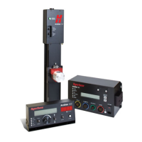
Torch Lifter Requirement
The HT4400 system requires a high-quality, motorized torch lifter with sufficient travel to cover all cutting thickness
requirements. The lifter must provide 10 inches (254 mm) of vertical travel. The unit should have a constant
speed of at least 20 ipm (508 mm/min) with positive braking. A unit which drifts through the stop point is not ac-
ceptable.
Use 2 wrenches when tightening to prevent damage to the mating component.
• Install the water cooler, the ignition console and connecting coolant hoses at a lower height than the torch to
prevent leaking when the torch body is disconnected from the torch leads.
Use the HT4400 System Connections diagram later in this section to help make the system cable, torch and hose
connections. Follow the number guide on the diagram to find out specific information on each cable, hose or con-
nection. The numbered items are detailed on the pages following the diagram.
System Units Placement
• Position all required units prior to making electrical, gas and interface connections.
• Ground all external modules in the HT4400 system to earth.
• To prevent leaks in the system, tighten all gas and water connections to the following specifications:
Gas or Water
Torque Specification
Hose Size
lbf-in lbf-ft kgf-cm
Up to 3/8" (9.5 mm) 75-85 6.25-7 86-98
1/2" (12 mm) 360-480 30-40 415-550

 Loading...
