MAINTENANCE
HT4400 Instruction Manual 5-33
3
Return analog PCB3 connectors PL3.6, PL3.9, PL3.5 and PL3.7 to their original positions.
6. If a chopper does not output +360 VDC, check to see if LED1 logic power light is illuminated. If LED1 is
extinguished, check if 120V is going to JP6. If there is no 120V at JP6, check wiring back to power
distribution board. Repair or replace any defective components. Also check to see if LED3 is turning green
when start command is given (normal condition). If LED1 is illuminated and LED3 is red when start
command is given (fault condition), then make sure that JP9 is seated properly.
7. If a chopper still does not output +360 VDC after completing these instructions through step 6, there may
be a problem with the control signal or the chopper module. The chopper drive signal comes through the
analog board PCB3 as an analog level from 0 to +6.2 VDC, which varies the duty cycle and subsequent
output current of the chopper. These analog signals are on PCB3 pins 5&6 PL3.9 for CH1, pins 5&6 PL3.5
for CH2, pins 5&6 PL3.6 for CH3, and pins 5&6 PL3.7 for CH4.
To check choppers in non-transferred mode:
• Ensure that solid-state ignition is still disabled (see step 1).
• On analog board PCB3, disconnect PL3.9 from REC9 (to test CH1), or disconnect PL3.5 from REC5 (to test CH2), or
disconnect PL3.6 (to test CH3), or disconnect PL3.7 (to test CH4). LED3 should be green.
• Place voltmeter across the output of the chopper in test and give the START command.
• If the voltmeter reads +360 VDC, then there is a problem with either control board PCB2 or analog board PCB3.
• If the voltmeter reads 0 volts, then replace the chopper module.
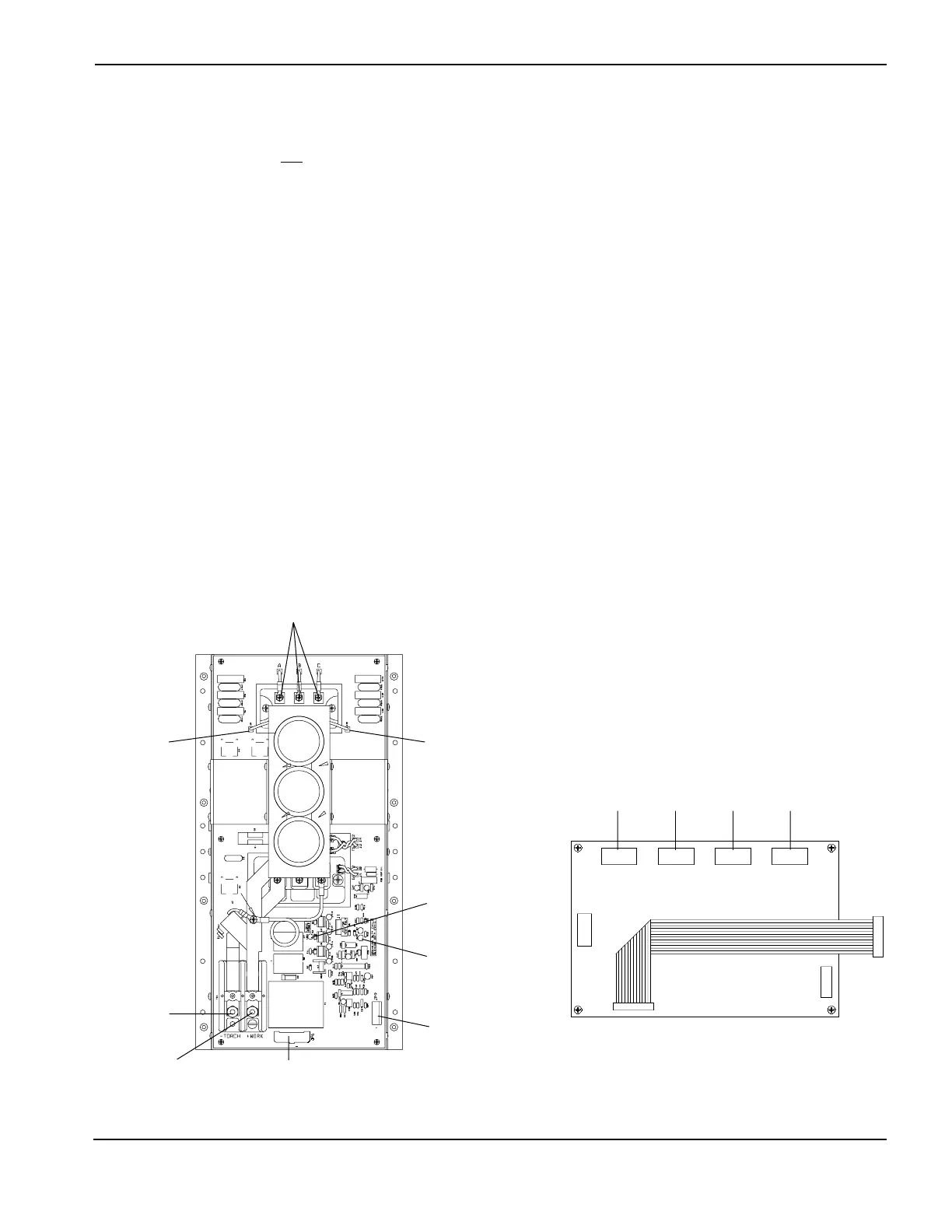
Chopper Module - Front View
Analog PCB3
3ø Input
Bridge (+) Bridge (-)
LED1
PL3.9
REC9 REC5 REC6 REC7
(+) Work
Torch (-)
LED3
JP9
JP6
PL3.5 PL3.6 PL3.7
 Loading...


