APPENDIX C – BEVEL CUTTING
c-4 HPR260 Manual Gas Instruction Manual
4
Cut charts
Initial pierce heights and pierce delay times listed in the cut charts are for straight cuts. Edge start indicates that the
material thickness is outside the range that can be pierced. These thicknesses can only be cut by using an edge start.
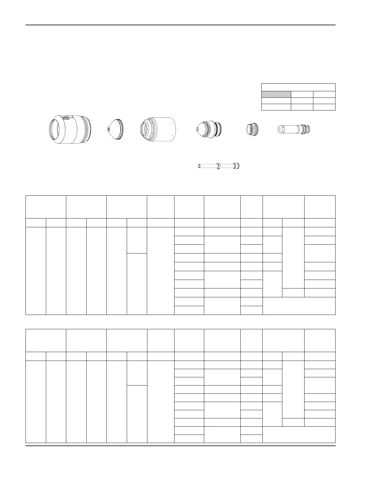
Mild steel bevel cutting
O
2
Plasma / Air Shield
130 A
220645220398 220649220603 220179220646
Notes: Bevel angle range is 0° to 45°. Water tube 220700 must be used with these
consumables.
Flow rates – lpm/scfh
O
2
Air
Preflow 0 / 0 64 / 135
Cutflow 33 / 70 45 / 96
Metric
English
Select
Gases
Set
Preflow
Set
Cutflow
Minimum
Clearance
Equivalent
Material
Thickness
Torch-to-Work
Distance
Cutting
Speed
Initial Pierce
Height
Pierce Delay
Time
Plasma Shield Plasma Shield Plasma Shield mm
mm
mm mm/m mm factor % seconds
O
2
Air 15 23 80
30
2.0
3
2.5 – 8.6 6505 5.0
200
0.1
4
2.8 – 8.6
5550
5.6
0.2
6
4035
0.3
23
10
3.0 – 8.6 2680 6.0
12
3.3 – 8.6 2200 6.6 0.5
15
3.8 – 8.6
1665
7. 6
0.7
20
1050 1.0
25
4.0 – 8.6 550 190 1.8
32
4.5 – 8.6
375
Edge start
38
255
Select
Gases
Set
Preflow
Set
Cutflow
Minimum
Clearance
Equivalent
Material
Thickness
Torch-to-Work
Distance
Cutting
Speed
Initial Pierce
Height
Pierce Delay
Time
Plasma Shield Plasma Shield Plasma Shield in
in
in ipm in factor % seconds
O
2
Air 15 23 80
30
0.080
0.135
0.100 – 0.340 240 0.200
200
0.1
3/16
0.110 – 0.340
190
0.220
0.2
1/4
150
0.3
23
3/8
0.120 – 0.340 110 0.240
1/2
0.130 – 0.340 80 0.260 0.5
5/8
0.150 – 0.340
60
0.300
0.7
3/4
45 1.0
1
0.160 – 0.340 20 190 1.8
1-1/4
0.180 – 0.340
15
Edge start
1-1/2
10

 Loading...


