TABLE OF CONTENTS
Service Manual
SECTION 5 PARTS LIST - CE ..................................................................................................... 5-1
Power Supply - 400V CE ..................................................................................................................................... 5-2
PAC121TS Torch Assembly .............................................................................................................................. 5-10
PAC121MS Torch Assembly ............................................................................................................................. 5-11
Consumable Parts - CE ..................................................................................................................................... 5-12
Powermax800 Field Upgrade Kits and Optional Parts ....................................................................................... 5-13
Power Supplies - 400V CE ................................................................................................................................ 5-13
Recommended Spare Parts - Powermax800 - 400V CE ................................................................................... 5-14
SECTION 6 WIRING DIAGRAMS ................................................................................................ 6-1
Powermax800 Electrical Schematic: 208/240/480V ............................................................................................ 6-2
Powermax800 Electrical Schematic: 200/230/400V ............................................................................................ 6-3
Powermax800 Electrical Schematic: 400V CE .................................................................................................... 6-4
Powermax800 Troubleshooting Schematic 1 of 2 ............................................................................................... 6-5
Powermax800 Troubleshooting Schematic 2 of 2 ............................................................................................... 6-6
Powermax800 CE Troubleshooting Schematic 1 of 2 ......................................................................................... 6-7
Powermax800 CE Troubleshooting Schematic 2 of 2 ......................................................................................... 6-8
APPENDIX A AERATION MANIFOLD FOR CUTTING ALUMINUM ............................................ a-1
APPENDIX B STANDARDS INDEX............................................................................................... a-2
ILLUSTRATIONS
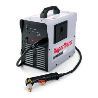
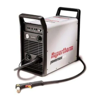
Figure 2-1 Powermax800 Hand Plasma Cutting System ................................................................................ 2-2
Figure 2-2 Powermax800 Power Supply with Dimensions .............................................................................. 2-3
Figure 2-3 PAC121TS Torch with Dimensions ................................................................................................ 2-4
Figure 2-4 PAC121MS Torch with Dimensions ............................................................................................... 2-4
Figure 2-5 S Mark Label ................................................................................................................................. 2-5
Figure 3-1 Filter Assembly ............................................................................................................................... 3-2
Figure 3-2 Air Filter Removal ........................................................................................................................... 3-3
Figure 3-3 Inverter Links .................................................................................................................................. 3-4
Figure 3-4 Single-Phase, 240 or 208V Block Diagram .................................................................................... 3-5
Figure 3-5 Back Side of Power Board - Test Points ...................................................................................... 3-27
Figure 3-6 Control Board Test Points ............................................................................................................ 3-29
Figure 3-7 PAC121TS Torch Main Body Removal ........................................................................................ 3-32
Figure 3-8 PAC121TS Torch Switch Removal .............................................................................................. 3-33
Figure 3-9 PAC121MS Torch Assembly ........................................................................................................ 3-35
Figure 3-10 Quick Disconnect O-Ring Removal and Replacement ................................................................. 3-36
Figure 4-1 Powermax800 - Front ..................................................................................................................... 4-3
Figure 4-2 Powermax800 - Top and Right Side .............................................................................................. 4-5
Figure 4-3 Powermax800 - Bottom and Left Side ............................................................................................ 4-7
Figure 4-4 Powermax800 - Rear ..................................................................................................................... 4-9
Figure 4-5 PAC121TS Torch Assembly and Leads ....................................................................................... 4-10
Figure 4-6 PAC121MS Torch Assembly and Leads ...................................................................................... 4-11
Figure 4-7 Consumable Parts ........................................................................................................................ 4-12
Figure 5-1 Powermax800 CE - Front ............................................................................................................... 5-3
Figure 5-2 Powermax800 CE - Top and Right Side ........................................................................................ 5-5
Figure 5-3 Powermax800 CE - Bottom and Left Side ...................................................................................... 5-7
Figure 5-4 Powermax800 CE - Rear ............................................................................................................... 5-9
Figure 5-5 PAC121TS Torch Assembly and Leads ....................................................................................... 5-10
Figure 5-6 PAC121MS Torch Assembly and Leads ...................................................................................... 5-11
Figure 5-7 Consumable Parts - CE ................................................................................................................ 5-12
Figure a-1 Aeration Manifold ........................................................................................................................... a-1
iv
9-96
 Loading...
