OPERATION
0
4-14 powermax1000 Operator Manual
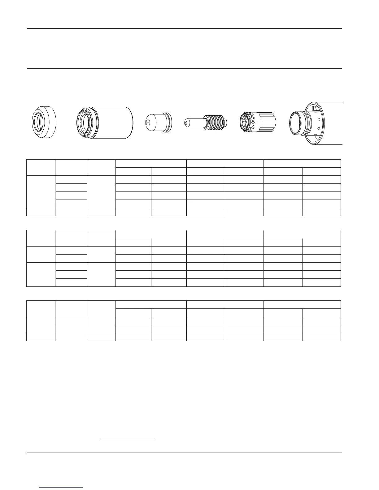
40 Amp Unshielded Consumables
• Torch-to-work distance for the following cut chart is 1/16 inch (1.5 mm) for all cuts.
Retaining Cap
120928
Nozzle
220006
Electrode
120926
Swirl Ring
120925
T60M
Torch
Deflector
120979
Mild Steel
Inches mm IPM mm/min IPM mm/min
125 26 GA 0.5 550 13970 353 8966
128 22 GA 0.8 484 12294 315 8001
130 18 GA 1.3 238 6045 155 3937
131 16 GA 1.5 167 4242 109 2769
40 129 0.25 14 GA 1.9 326 8280 212 5385
Stainless
Inches mm IPM mm/min IPM mm/min
127 26 GA 0.5 561 14249 365 9271
127 22 GA 0.8 453 11506 295 7493
123 18 GA 1.3 500 12700 325 8255
127 16 GA 1.5 367 9322 239 6071
128 14 GA 1.9 220 5588 143 3632
Aluminum
Inches mm IPM mm/min IPM mm/min
125 1/32 0.8 564 14326 366 9296
127 1/16 1.5 236 5994 153 3886
40 127 0.25 3/32 2.4 261 6629 170 4318
Arc
Current
Material Thickness
25
25
Arc
Voltage
Pierce
Delay
0
Arc
Current
Optimum Travel SpeedsMaterial Thickness Maximum Travel Speeds
Optimum Travel SpeedsMaximum Travel SpeedsMaterial Thickness
Optimum Travel Speeds
25
40
0
0.25
Arc
Current
Arc
Voltage
Pierce
Delay
0
Arc
Voltage
Pierce
Delay
Maximum Travel Speeds
Maximum travel speeds are the fastest travel speeds possible to cut the material without regard to cut quality.
Optimum travel speeds provide the best cut angle, least dross and best cut surface finish. Remember that cut charts
are intended to provide a good starting point
for each different cut assignment. Every cutting system requires
“fine tuning” for each cutting application in order to obtain the desired cut quality.

 Loading...


