EasyManuals Logo
Home>Hypertherm>Welding System>Powermax45 XP

Hypertherm Powermax45 XP Field Service Bulletin

Hypertherm Powermax45 XP
30 pages
To Next Page IconTo Next Page
To Previous Page IconTo Previous Page
Page #14 background imageLoading...
Page #14 background image
Machine Interface Receptacle with Voltage Divider Board
14 809940 Field Service Bulletin Powermax45 XP
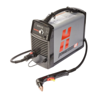
6. Make sure that the ground clip is connected
to the ground wire.
7. Put the ground clip into position to align with the
screw from the handle.
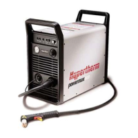
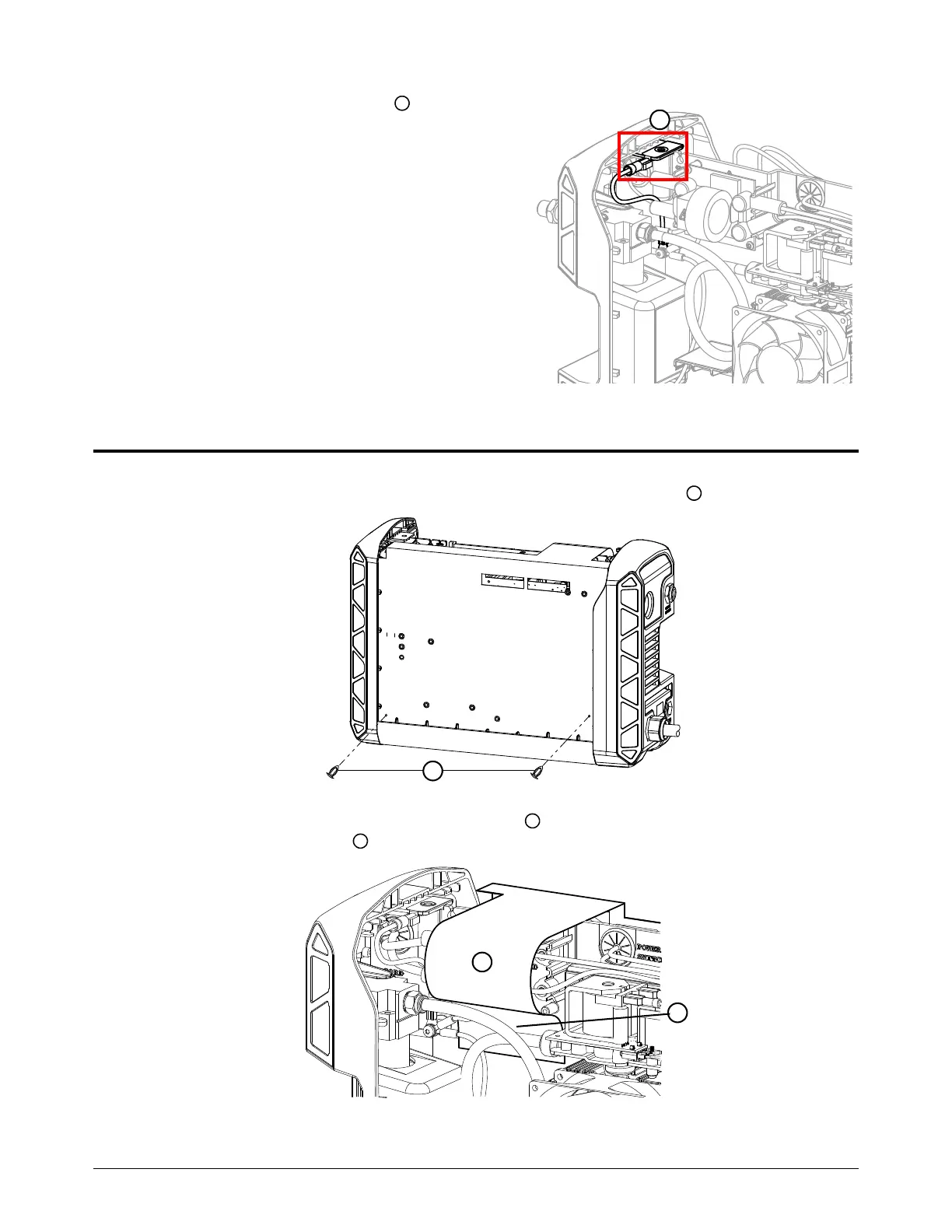
Install the external components
1. Attach the component barrier to the power PCB with the 2 plastic pins .
2. Put the extended piece of the component barrier above the power cord connection points
and behind the gas hose .
7
1
1
2
3
2
3

Other manuals for Hypertherm Powermax45 XP

Questions and Answers:

Question and Answer IconNeed help?

Do you have a question about the Hypertherm Powermax45 XP and is the answer not in the manual?

Hypertherm Powermax45 XP Specifications

General IconGeneral
BrandHypertherm
ModelPowermax45 XP
CategoryWelding System
LanguageEnglish

Related product manuals