OperatiOn
4-2 powermax
65/85
Operator Manual
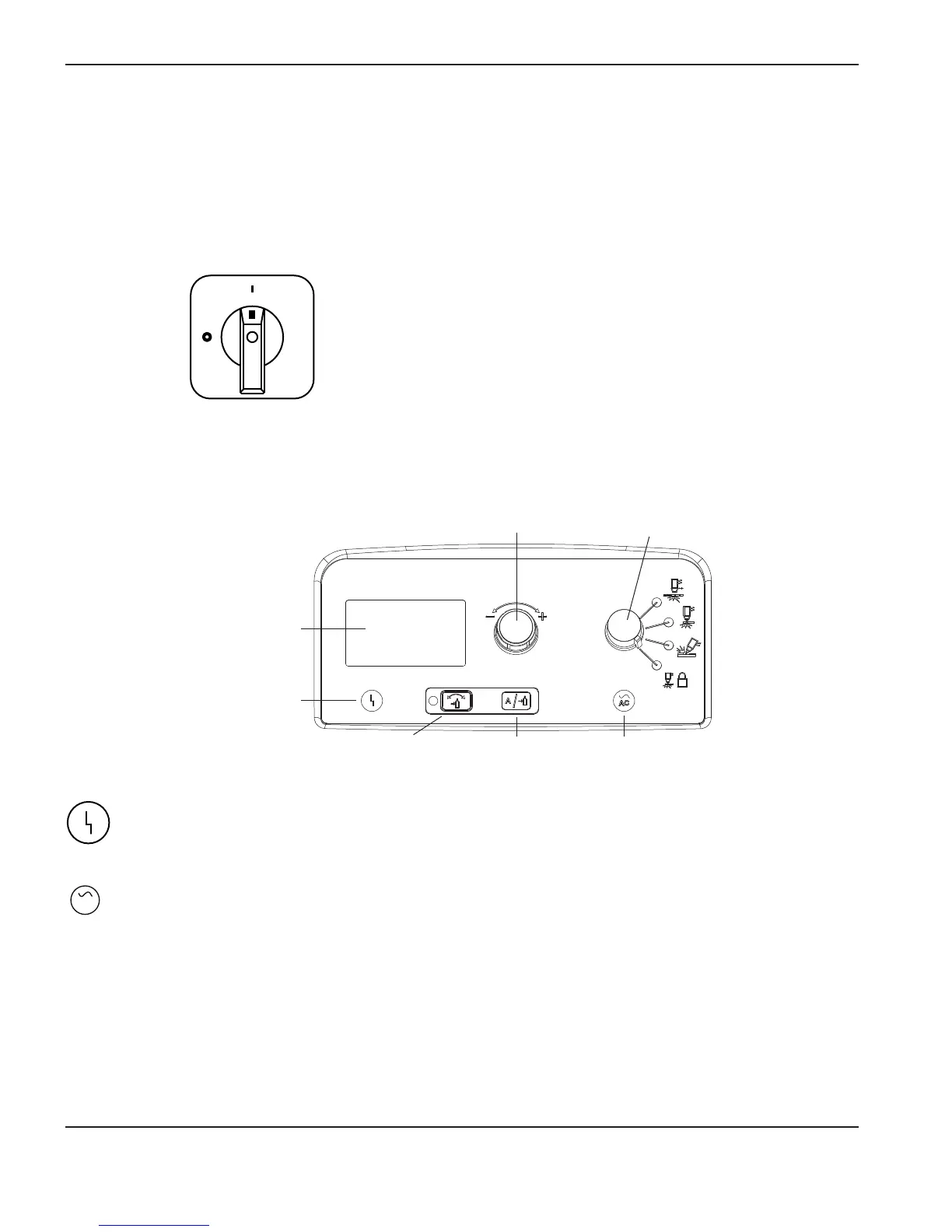
Front controls and LEDs
Controls and indicators
The Powermax65 and Powermax85 power supplies have the following: ON/OFF switch, adjustment knob,
automatic/ manual pressure setting mode selector, current/gas selector, operating mode switch, indicator LEDs, and
astatus screen.
Rear controls
ON (I)/OFF (O) power switch
Activates the power supply and its control circuits.
Power ON LED (green)
When illuminated, this LED indicates that the power switch has been set to I (ON) and that the safety interlocks
are satisfied. When blinking, the power supply has a fault.
Fault LED (yellow)
When illuminated, this LED indicates that there is a fault with the power supply. For information about these
fault conditions and how to correct them, refer to section 5.
AC
Power ON LED
(green)
Automatic/manual pressure
setting mode selector
Current/gas
selector
Operating
mode switch
Adjustment knob
Fault LED
(yellow)
Status screen

 Loading...