Torch SeTup
3-24 powermax
65/85
Operator Manual
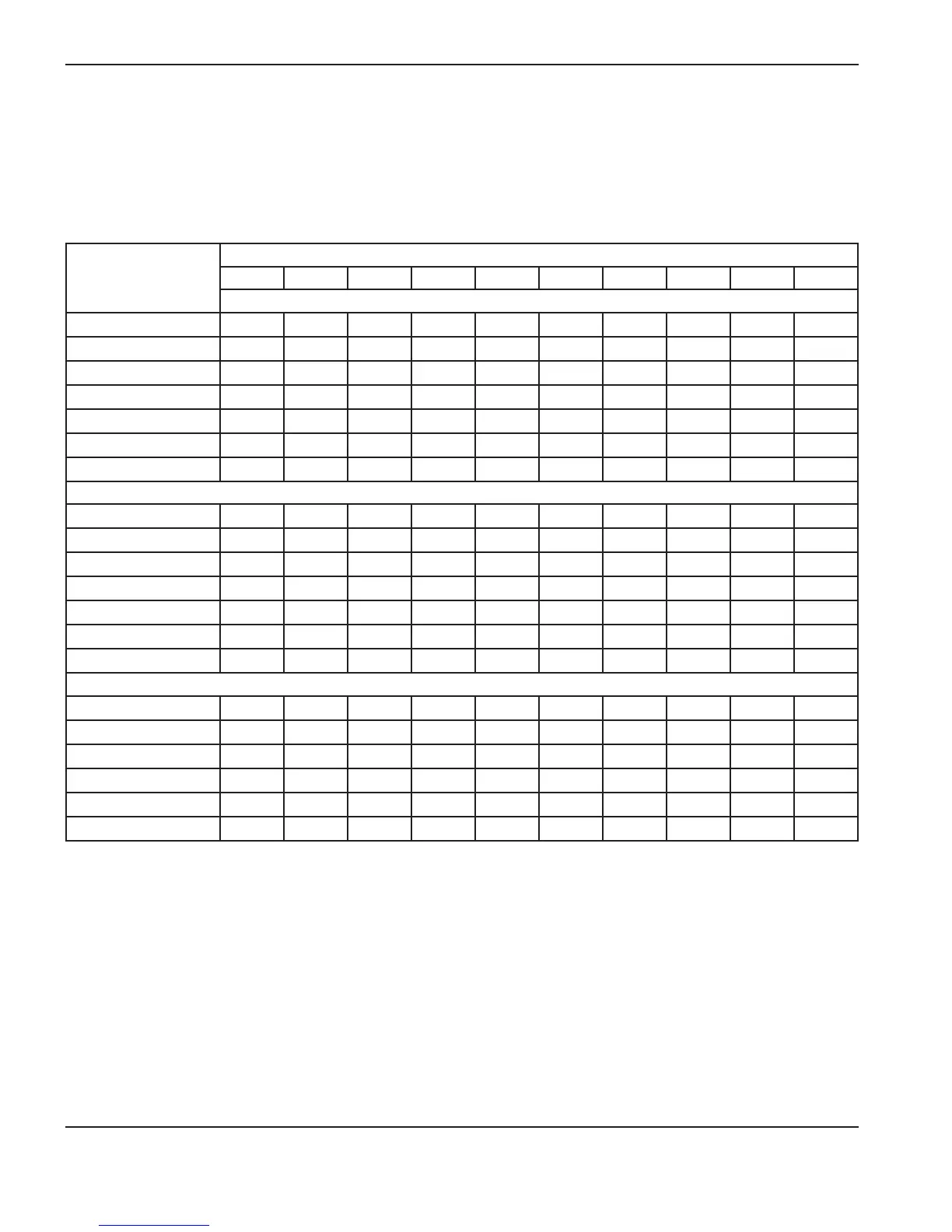
Estimated kerf-width compensation
The widths in the tables below are for reference. The data are obtained with the “Best Quality” settings. Differences
between installations and material composition may cause actual results to vary from those shown in the tables.
Estimated kerf-width compensation – Metric (mm)
Process
Thickness (mm)
0.5 1 2 3 6 8 10 12 16 20
Mild Steel
85A Shielded 1.7 1.8 1.9 2.0 2.2 2.4 2.6
65A Shielded 1.6 1.6 1.8 1.9 2.0 2.2 2.3
45A Shielded 1.1 1.1 1.4 1.5 1.7
FineCut 0.7 0.7 1.3 1.3
85A Unshielded 1.7 1.8 1.9 2.0 2.1 2.1 2.3
65A Unshielded 1.6 1.6 1.7 1.8 1.9 2.0
45A Unshielded 0.5 0.9 1.3 1.3
Stainless Steel
85A Shielded 1.6 1.8 1.9 2.1 2.3 2.4 2.5
65A Shielded 1.4 1.5 1.8 1.9 2.0 2.2 2.4
45A Shielded 0.9 1.1 1.5 1.6 1.8
FineCut 0.6 0.6 1.4 1.5
85A Unshielded 1.7 1.7 1.8 1.9 2.1 2.2 2.4
65A Unshielded 1.6 1.6 1.8 1.8 1.9 2.0
45A Unshielded 0.5 1.0 1.3 1.5 1.5
Aluminum
85A Shielded 2.0 1.9 2.0 2.1 2.2 2.4 2.6
65A Shielded 1.9 1.9 1.9 2.0 2.1 2.3 2.5
45A Shielded 1.5 1.5 1.6 1.5
85A Unshielded 1.9 1.9 1.9 2.0 2.0 2.1 2.2
65A Unshielded 1.8 1.8 1.8 1.8 1.9 2.0
45A Unshielded 1.6 1.5 1.4 1.5

 Loading...