MAINTENANCE
3-10
Service Manual
1. Set the Powermax900 power switch to O (off), unplug the power cord, and disconnect the
gas supply.
2. Remove the cover of the power supply by removing the securing screws.
3. Visually inspect the inside of the power supply, especially on the side with the power board
(see Figure 4-3). Look for broken or loose wiring connections, burn and char marks,
damaged components, etc. Repair or replace as necessary.
Resistance Checks
All resistance values in this section were taken with the power cord disconnected, all internal
power supply wires attached, and with the torch unplugged. Perform
Visual Inspection -
Internal
before continuing in this section.
• If your resistance values are not close to the values given in this section, isolate the problem
by removing wires attached to the resistance check points or component until the problem is
found.
• After the problem has been located and repaired, refer to the
Sequence of Operation
flow
diagram in this section to test the power unit for proper operation.
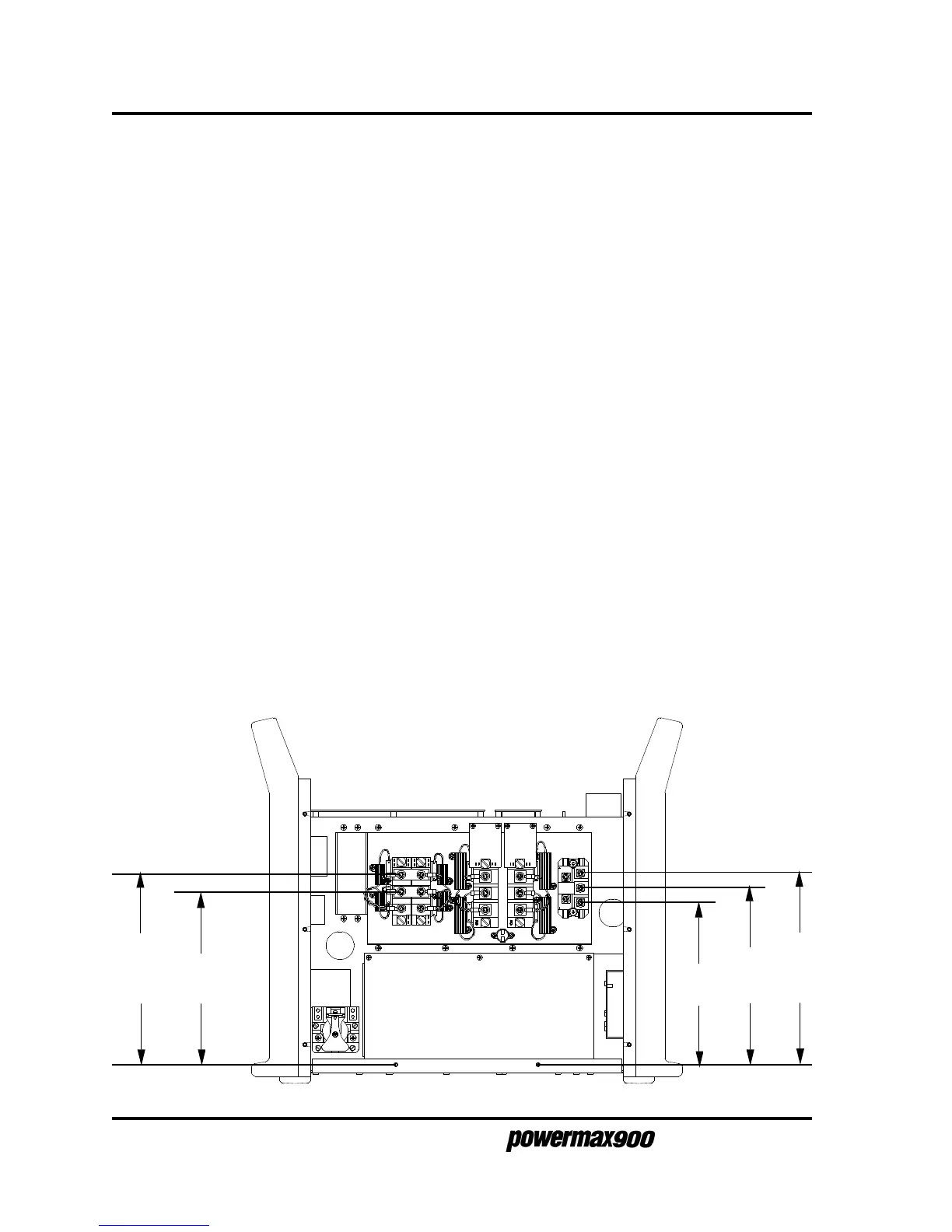
Resistance Check #1 - Fig. 3-8
• Input to Chassis
Inputs to the chassis are open (greater than 50MΩ).
• Output to Chassis
Outputs to the chassis are open (greater than 50MΩ).
> 50MΩ
> 50MΩ
> 50MΩ
> 50MΩ
> 50MΩ
Figure 3-8 Resistance Check #1 - Input to Chassis, Output to Chassis
 Loading...


