3-25
MAINTENANCE
Service Manual
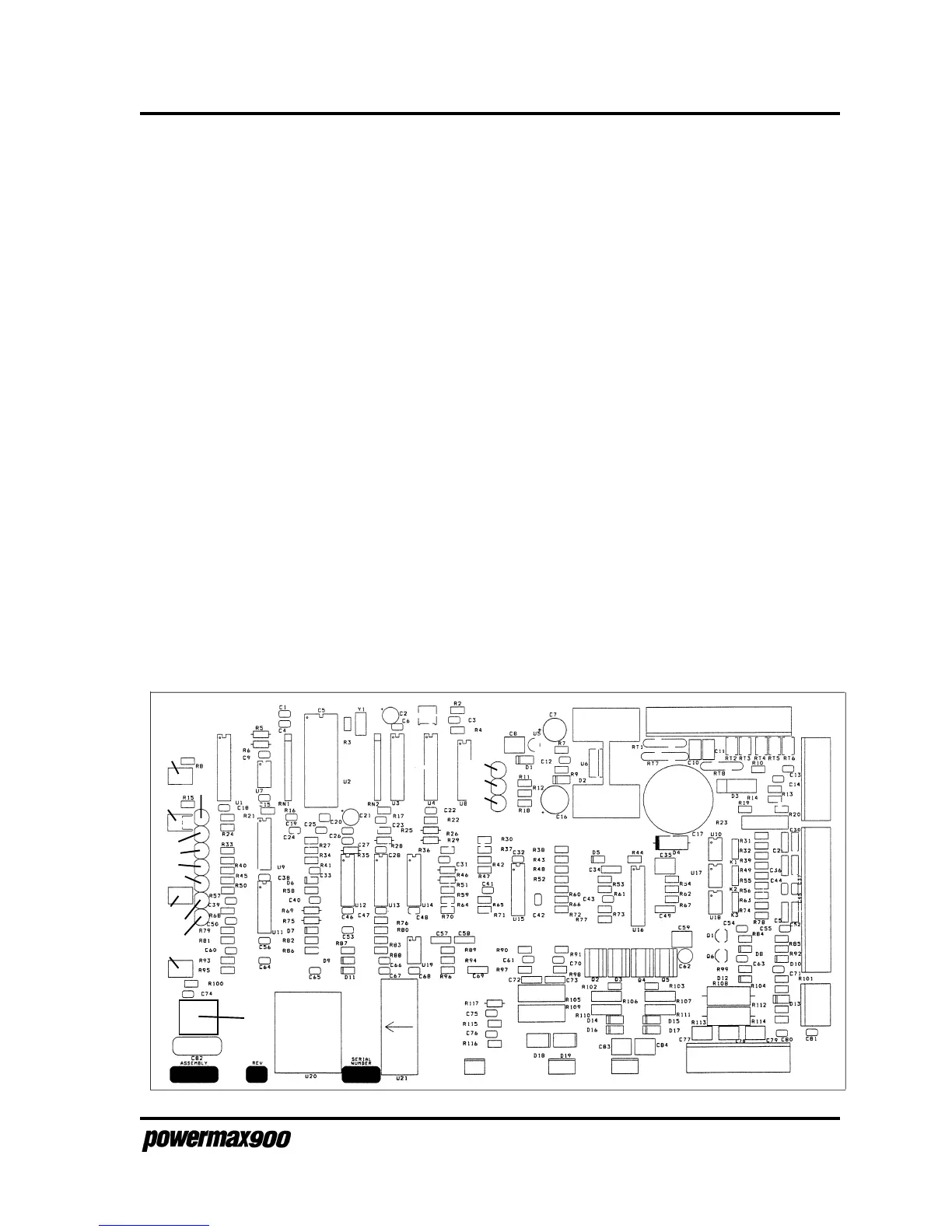
Figure 3-16 Control Board LED Locations
J8
J1
J3
J4
J7
J6J5
TP5 (Gnd)
J2
LED3
LED1
LED4
R1
LED2
LED5
LED6
LED7
LED8
LED9
LED10
LED11
LED12
LED13
LED14
S1
9-99
The control board also controls the sequence required to generate plasma:
• Turns on the inverter approximately 1 second after the torch trigger switch is pressed
• After a short delay, turns on the gas solenoid valve V1 to blow back the electrode
• Monitors the pilot arc for arc transfer
• Ramps the current control command from the pilot arc level (22 amps) to the cut current selected by the
operator
• Turns the inverter off if the output current fails for any reason
• Turns the inverter off if the torch blow back does not occur within 2 seconds
• Turns off the power supply when the retaining cap is loose or when line voltage is too high.
• LED6 PLASMA START: Illuminates when the torch start button is pushed or when start
button is activated from the machine interface.
• LED7 INVERTER ON: Illuminates when the command to turn on the inverter modulator is
given.
• LED8 CURRENT: Illuminates when current greater than 10 amps is detected in electrode
circuit.
• LED9 BLOWBACK: Illuminates when more than 25 arc volts is detected.
• LED10 ARC TRANSFER: Illuminates when arc transfers to the workpiece (when arc current
is greater than 1.5 amps).
• LED12 OVERCURRENT: Illuminates when CS1 or CS2 senses current above 70 amps.
Release the START switch to clear.
• LED13 FAULT: Illuminates when there is either an overvoltage condition, an imbalance in the
inverters, or a micro-controller failure.
 Loading...


