Possible failing
component FRU name Position
Type or CCIN
number (see the
Type, model, and
part number list)
Remove and
replace
procedure
Additional
comments
Tape unit Tape unit D08 See the Type,
model, and part
number list
Go to Models
270, 800, and 810
- Removable
media - D07 and
D08
Air moving device
(AMD)
AMD B01, B02 See Final
assembly —
Models 270, 800,
and 810
Go to Models
270, 800, and 810
- Air moving
device (AMD)
B01; B02
Power supply Power supply P01 See Final
assembly -
Models 270, 800,
and 810
Go to Models
270, 800, and 810
- Power supply -
P01
Control panel Control panel NB1 247D (See page
523)
Go to Models
270, 800, and 810
- Control panel -
NB1
Processor
regulator
Processor
regulator
R01 04N4276 Go to Models
270, 800, and 810
- Processor
regulator - R01
Device board Device board DB1 283E (See page
526)
(non-concurrent),
28CD (See page
528) (concurrent)
Go to Models
270, 800, and 810
- Device board
Time of day
battery
Time of day
battery
MB1 Go to Models
270, 800, and 810
- Time of day
battery
HSL cables HSL cables Attached to active
HSL ports
Go to HSL cables
- concurrent
Memory configuration
A single main storage DIMM feature is allowed on all Models 800 and 810 (except processor features
7428 and 7430).
When the total number of main storage DIMMs is increased greater than one, the single existing DIMM
must be paired up (with a DIMM of the same capacity) and any additional DIMMs must be added in pairs
of the same capacity. Memory pairs are to be in the following order: A/B, C/D, E/F, G/H.
There are 8 memory DIMM slots available in the base system for main storage DIMMs which plug directly
onto the backplane.
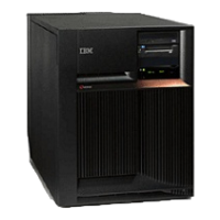
Figure 3. Models 800 and 810 System Unit Expansion
Analyze hardware problems 247
 Loading...


