6. The following table provides information necessary to identify the IOP to which IOAs are assigned.
v The left column indicates the domain in which IOA assignment is allowed.
v The right column is used to determine the IOP to which an IOA is assigned.
v The first position in the list must be an IOP. The remaining positions may be IOPs or IOAs. IOAs are
assigned to the first IOP located to their left in the list. Although IOAs can be manually reassigned
using SST/DST, the IOA assignments return to the default order after each IPL.
Table
2. Identify the IOP to which IOAs are assigned
Multi-adapter bridge domain / PCI bridge set IOA assignment rules
C01 - C04 C01, C02, C03, C04
C05 - C09 C05, C06, C07, C08, C09
C11 - C15 C11, C12, C13, C14, C15
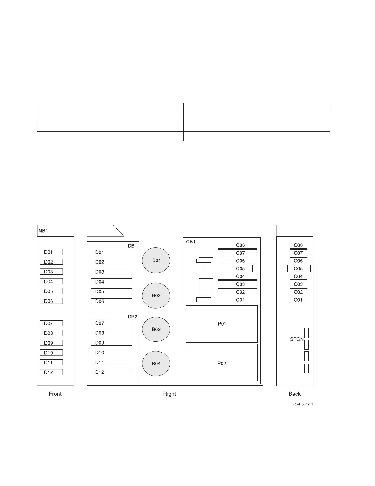
Locations — FC 5095, FC 0595 Expansion I/O Tower
For use by authorized service providers.
The following diagrams show field replaceable unit (FRU) layout in the FC 5095, FC 0595 Expansion I/O
Tower. Use them with the tables below. If you need address information, refer to Addresses — FC 5095,
FC 0595 Expansion I/O Tower.
Figure 1. FC 5095 Expansion I/O Tower
Figure 2. FC 0595 Expansion I/O Tower
312 Hardware (Remove and Replace; Part Locations and Listings)
 Loading...


