d. Remove the screws that hold the PCI card enclosure to the frame.
e. Pull the PCI card enclosure partially out of the frame while lifting the cables clear of the enclosure.
f. Press the release mechanism that is located along the top right side of the enclosure and carefully
slide the enclosure towards you. Make sure that the cables are clear of the enclosure.
g. Remove the battery charger. See FC 5074, FC 5079, FC 9079 (with single line cord) - AC charger
- A01.
h. Remove the power supplies. See FC 9074, FC 9079, FC 5074/5079 - Power supply - P01, P02,
and P03.
i. Remove the blank filler plate(s).
j. Remove the four batteries (see FC 5074, FC 5079, FC 9079 - Batteries - T01, T02, T03, and T04).
3.
Remove the screws from the power subframe assembly.
4. From the front of the tower, reach through the frame and remove the cables from the backside of the
power distribution backplane and note their locations.
5. From the rear of the tower, remove the mounting screws that hold the power distribution backplane to
the frame.
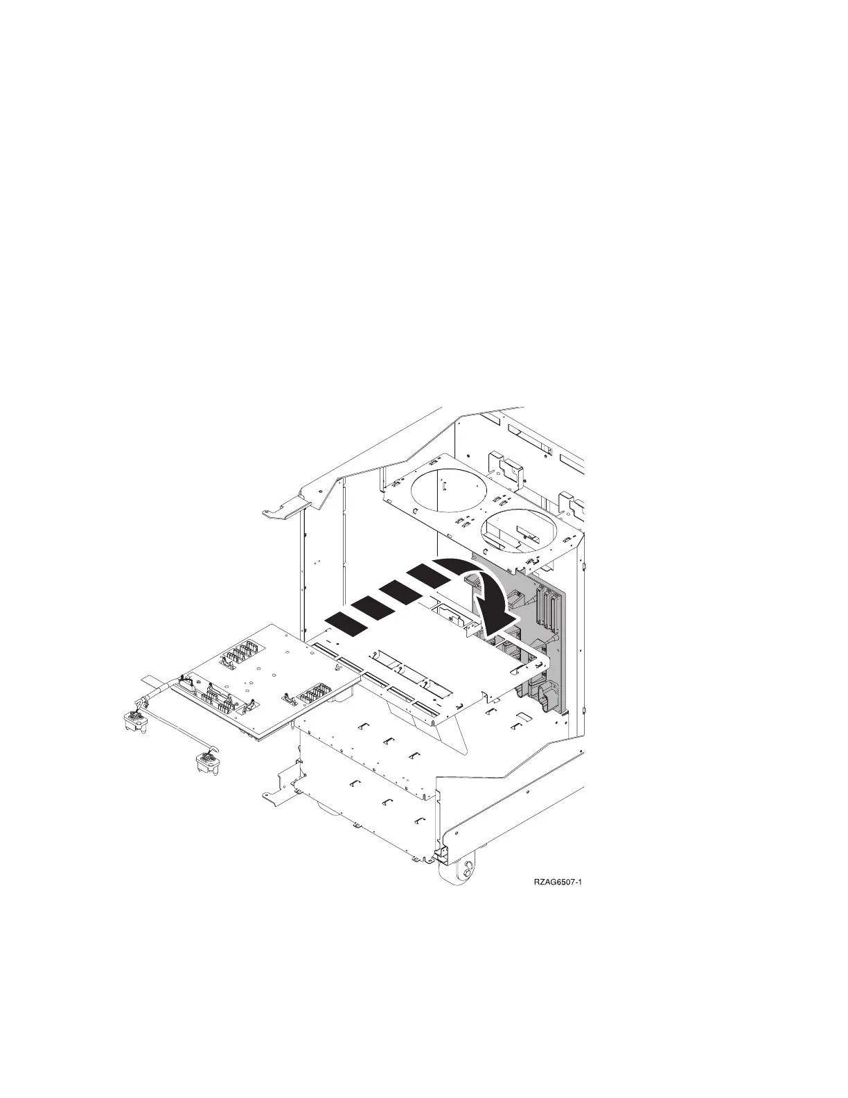
6. Pull the power distribution backplane slightly towards you and lift it up to remove it from the frame.
7. Install the power distribution backplane by reversing the removal procedure. After exchanging an item,
go to “Verify the repair” on page 558.
This ends the procedure.
FC 5074, FC 5079, FC 9074, FC 9079 - Power supply - P00, P01, P02, and P03
For use by authorized service providers.
Analyze hardware problems 149
 Loading...


