The device fans are xed inside the fan assemblies to provide necessary airflow to cool the whole system.
Two fans are located in each unit. The system software sets the speed and measures it through the
tachometer interface.
Observe the following operational notes for fan assemblies in the device:
• The three fan assemblies that are concurrently installed in the chassis must be of the same power type,
model (airflow direction), and part number. If the airflow directions are different, an error is generated
on the console.
• The fan assembly units are hot-swappable and can be replaced one at a time. They are identical and
install into any fan slot.
• The device can operate all the ports with one faulty fan assembly if you do not require redundancy.
Precautions specic to the fan assemblies
CAUTION: Disassembling any part of the power supply and fan assembly
voids the warranty and regulatory certications. There are no user-
serviceable parts inside the power supply and fan assembly.
CAUTION: Ensure that the airflow direction of the power supply unit
matches that of the installed fan tray. The power supplies and fan trays
are clearly labeled with either a green arrow with an "E", or an orange arrow
with an "I."
CAUTION: If you do not install a module or a power supply in a slot, you
must keep the slot ller panel in place. If you run the chassis with an
uncovered slot, the system will overheat.
CAUTION: To prevent damage to the chassis and components, never
attempt to lift the chassis using the fan or power supply handles. These
handles were not designed to support the weight of the chassis.
Note: The equipment installation must meet NEC/CEC code requirements. Consult local authorities for
regulations.
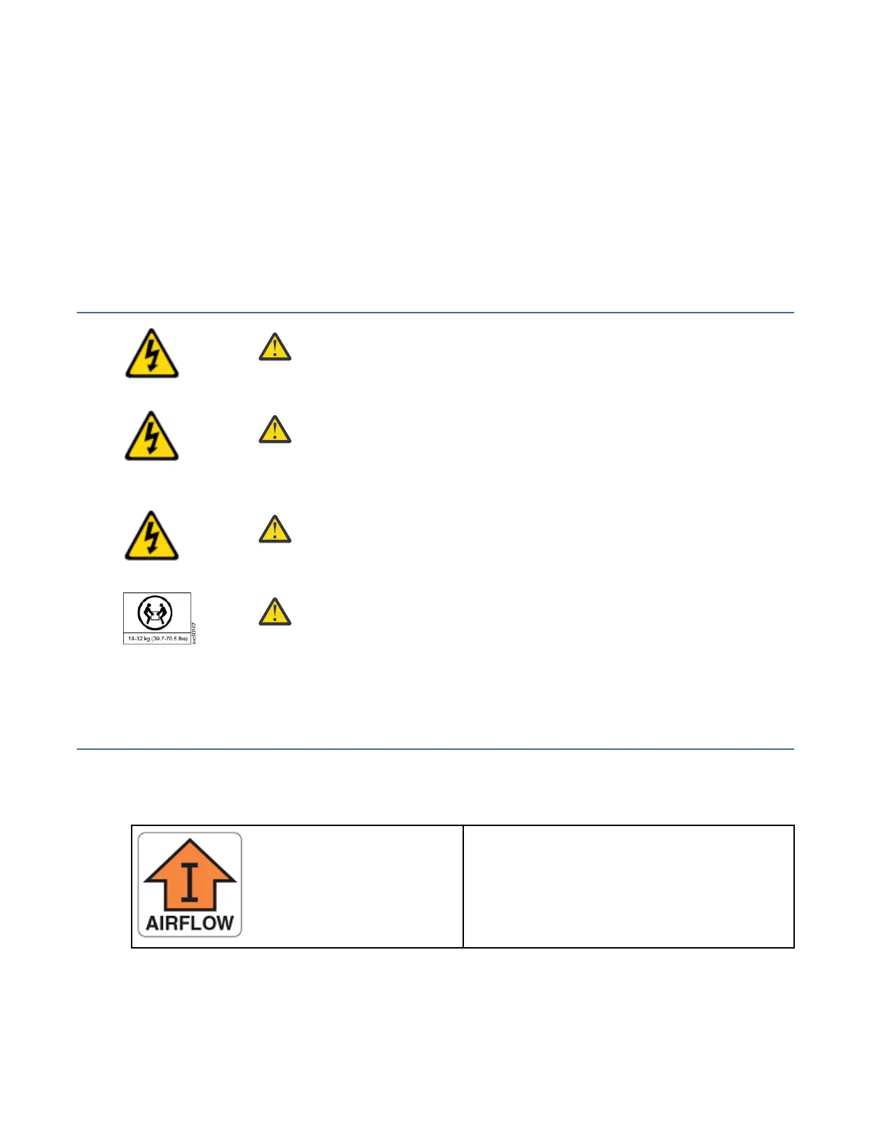
Identifying the airflow direction
The power supply and fan assemblies are identied by the following airflow directions:
• Intake power supply and fan assembly with an orange "I" label or without any label: Pulls air from
the nonport-side of the switch and exhausts it out the port side.
– Nonport-side air intake
– Port-side air exhaust
– Back-to-front (nonport-side to port-side)
airflow
– Part numbers ending with -R
• Exhaust power supply and fan assembly with a green "E" label: Pulls air from the port side of the
switch and exhausts it out the nonport-side.
62
IBM Storage Networking SAN128B-7: SAN128B-7 Installation, Service, and User Guide
 Loading...