to the system management interfaces; it can also be used for iSCSI
connectivity to the system by hosts on the network.
Note: On Storwize V5010 and Storwize V5020 systems, the second Ethernet
port is also used as the technician port. Do not connect Ethernet port 2 to
the SAN until the management GUI setup wizard completes on each system
and the cluster is created. If you have to service your system, disconnect
port 2 from the SAN before you enable port 2 to be the technician port
again.
2. If you have a Storwize V5030 or Storwize V5030F system, complete the
following steps.
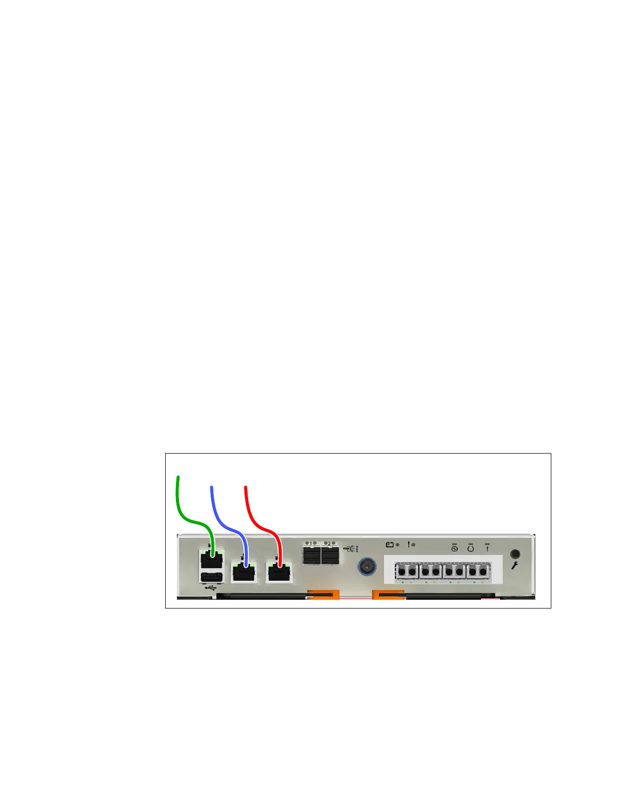
a. Identify the location and function of the Ethernet ports on your system;
refer to Figure 127.
v The technician port should only be used to initialize or service the
system. In Figure 127, the technician port is identified by the green cable.
Note: Never use the technician port to provide an Ethernet connection to
the system. Do not connect the Ethernet technician port to a network
switch. The technician port must only be directly connected to a personal
computer when initializing a system or servicing a node.
v Ethernet port 1 can be used to provide Ethernet connections. In the
figure, port 1 is identified by the blue cable.
v Ethernet port 2 can optionally be used to provide additional Ethernet
connections. In the figure, port 2 is identified by the red cable. Port 2 can
also be used for iSCSI connectivity or IP replication.
b. Connect Ethernet port 1 of each Storwize V5030 or Storwize V5030F node
canister in the system to the IP network that will provide a connection to
the system management interfaces. Figure 127 shows the port locations and
Ethernet cabling on a Storwize V5030 or Storwize V5030F node canister.
c. Optionally, connect Ethernet port 2 of each node canister in the system to a
second IP network, as shown by the red cable connection in Figure 127. Port
2 can provide a redundant connection to the system management interfaces.
Port 2 can also be used for iSCSI connectivity to the system by hosts on the
network. If more than one control enclosure is present in the system, ensure
that port 2 of every node canister is connected to the same network to
provide access if the configuration node fails.
Figure 127. Connecting the Ethernet cables to a Storwize V5030 or Storwize V5030F system
146 Storwize V5000 Gen2: Quick Installation Guide
 Loading...


