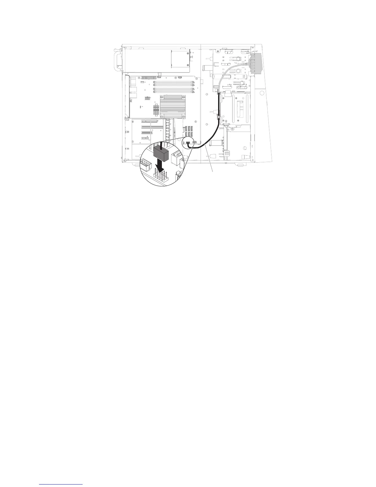
USB connector cable
11. Stand the server back up in its vertical position.
12. Install the upper bezel (see “Installing the upper bezel” on page 175).
13. Install the lower bezel (see “Installing the lower bezel” on page 173).
14. Install the and lock the side cover (see “Installing the side cover” on page
167).
15. Reconnect the external cables and power cords; then, turn on the attached
devices and turn on the server.
Removing the rear adapter retention bracket
This procedure applies only to the 5U server model with hot-swap power supplies
(Model name: 2582-F4x).
To remove the rear adapter-retention bracket on the 5U server model with hot-swap
power supplies (Model name: 2582-F4x), complete the following steps.
1. Turn off the server and all attached devices; then, disconnect all power cords
and external cables.
2. Unlock and remove the side cover (see “Removing the side cover” on page
166).
3. Carefully turn the server on its side so that it is lying flat, with the system board
facing up.
Attention: Do not allow the server to fall over.
4. Remove all adapters (if necessary) and place the adapters on a static-protective
surface (see “Removing a ServeRAID adapter” on page 176).
Note: You might find it helpful to note where each adapter is installed before
you remove the adapters.
5. Rotate the rear adapter-retention bracket to the open (unlocked) position.
6. Grasp the bracket on one side at the hinge point and pull inward (while you
rotate the bracket slightly toward the front of the server) until the bracket is free
of the hinge pin; then, grasp the bracket on the other side at the hinge point,
pull inward until the bracket is free of the hinge pin, and remove the rear
adapter-retention bracket from the server.
236 IBM System x3100 M4 Type 2582: Problem Determination and Service Guide
 Loading...


