EasyManua.ls Logo

IBM System x3250 4364 User Manual

IBM System x3250 4364
150 pages
To Next Page IconTo Next Page
To Previous Page IconTo Previous Page
Page #59 background image
1. Open the retaining clip on each end of the DIMM connector.
2. Touch the static-protective package that contains the DIMM to any unpainted
metal surface on the server. Then, remove the DIMM from the package.
3. Turn the DIMM so that the DIMM keys align correctly with the slot.
DIMM
Retaining
clip
4. Insert the DIMM into the connector by aligning the edges of the DIMM with the
slots at the ends of the DIMM connector. Firmly press the DIMM straight down
into the connector by applying pressure on both ends of the DIMM
simultaneously. The retaining clips snap into the locked position when the DIMM
is seated in the connector. If there is a gap between the DIMM and the retaining
clips, the DIMM has not been correctly inserted; open the retaining clips,
remove the DIMM, and then reinsert it.
5. Install the cover (see “Installing the cover” on page 29).
6. Slide the server into the rack.
7. If you disconnected any cables or power cords to replace the DIMM, connect
the cables and power cords.
8. Turn on all attached devices and the server.
Removing a fan
The server comes with five replaceable fans.
To remove any of the five replaceable fans, complete the following steps:
1. Read the safety information that begins on page vii and “Installation guidelines”
on page 25.
2. Turn off the server and all peripheral devices, and disconnect the power cords
and all external cables.
3. Remove the server from the rack and remove the cover (see “Removing the
cover” on page 28).
4. Reconnect the power cord; then, turn on the server.
Attention: For proper cooling and airflow, replace the cover before you turn
on the server. Operating the server for extended periods of time (more than 30
minutes) with the cover removed might damage server components.
5. Determine which fan to replace by checking the LEDs on the system board (see
“System-board LEDs” on page 9); a lit LED indicates the fan to replace.
6. Turn off the server; then, disconnect the power cord again.
Chapter 4. Removing and replacing server components 41

Table of Contents

Question and Answer IconNeed help?

Do you have a question about the IBM System x3250 4364 and is the answer not in the manual?

IBM System x3250 4364 Specifications

General IconGeneral
Form Factor1U Rack
MemoryUp to 8 GB
ProcessorIntel Xeon 3040
Memory TypeDDR2
StorageUp to 1.5TB
Storage ControllerIntegrated SATA
RAID SupportRAID 0, 1
Operating System SupportWindows Server, Linux
Processor CoresDual-Core

Summary

Safety

Guidelines for trained service technicians

Information for technicians on safe product servicing procedures.

Inspecting for unsafe conditions

Guidelines for identifying and assessing potential safety hazards in the product.

Guidelines for servicing electrical equipment

Specific safety advice for working with electrical components.

Safety statements

General statements and warnings related to product safety and usage.

Chapter 1. Introduction

Related documentation

Lists related IBM documentation for setup and optional devices.

Features and specifications

Details the server's technical specifications, dimensions, and environmental requirements.

Server controls, LEDs, and connectors

Identifies and explains the front and rear controls, indicator lights, and ports.

Chapter 2. Configuration information and instructions

Updating the firmware

Guides users through the process of updating the server's firmware.

Configuring the server

Explains methods and tools for configuring server hardware and settings.

Using the ServerGuide Setup and Installation CD

Instructions for using the ServerGuide CD for initial setup and OS installation.

Updating the DMI/SMBIOS data

Procedures for updating system management interface data.

Chapter 3. Parts listing, Type 4364, 4365, or 4366 server

Replaceable server components

Lists all components that can be replaced, with part numbers.

Product recovery CDs

Details the part numbers for various Microsoft Windows recovery CDs.

Chapter 4. Removing and replacing server components

Installation guidelines

Important safety and procedural recommendations before component work.

Handling static-sensitive devices

Essential precautions to prevent damage from electrostatic discharge.

Removing the cover

Step-by-step guide to safely remove the server's top cover.

Removing a memory module (DIMM)

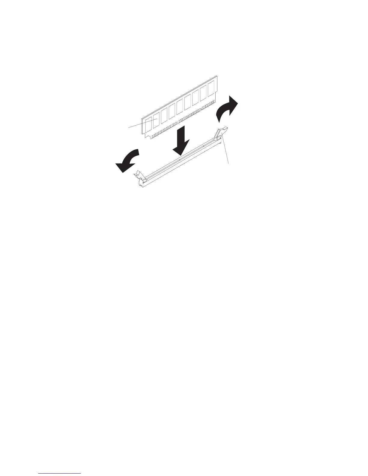
Procedure for removing a DIMM from its slot.

Installing a memory module (DIMM)

Procedure for installing a DIMM into its slot.

Removing the power supply

Instructions for safely removing the server's power supply.

Installing the power supply

Instructions for safely installing a replacement power supply.

Removing the system board

Step-by-step guide to remove the server's system board.

Installing the system board

Step-by-step guide to install a replacement system board.

Chapter 5. Diagnostics

Diagnostic tools

Overview of available tools for diagnosing server hardware issues.

POST

Explains the Power-On Self-Test and how it checks server components.

Error logs

Details how to access, view, and manage system error logs for diagnosis.

POST error codes

Lists POST error codes and recommended actions to resolve problems.

Troubleshooting tables

Provides tables correlating symptoms with potential solutions.

Solving undetermined problems

Guidance for diagnosing issues that lack specific error indicators.

Appendix A. Getting help and technical assistance

Before you call

Essential preparatory steps before contacting IBM support for assistance.

Hardware service and support

Information on how to obtain hardware service and support from IBM or resellers.

Appendix B. Notices

Trademarks

Lists IBM's registered trademarks and service marks.

Electronic emission notices

Statements regarding compliance with electronic emission standards like FCC and EMC.

Related product manuals