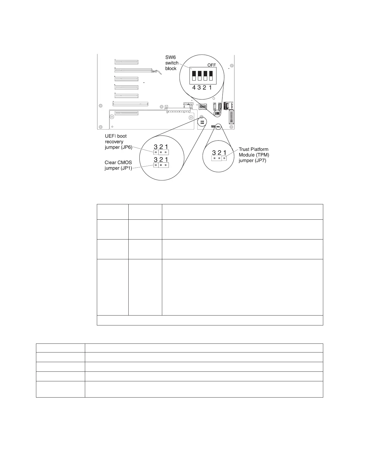
System-board switches and jumpers
The following tables show the settings of the switches and the jumpers.
Table 4. System-board jumpers
Jumper
number
Jumper
name Jumper setting
JP1 CMOS clear
v Pins 1 and 2: Normal operation (default).
v Pins 2 and 3: Clears CMOS memory.
JP6 UEFI boot
recovery
v Pins 1 and 2: Normal operation (default).
v Pins 2 and 3: Enable the UEFI recovery mode.
JP7 Trust
Platform
Module
(TPM)
v Pins 1 and 2: Physical presence to the TPM.
v Pins 2 and 3: No physical presence to the TPM (default).
Note: The physical presence requires manual setting on the
server to change the TPM configuration. The TPM is enabled
and physical presence is not asserted by default. The physical
presence needs to be asserted to activate, deactivate, clear or
change ownership of the TPM.
Note: If no jumper is present, the server responds as on default position.
Table 5. System-board switch 6
SW 6 Switches Switch description
1 Reserved (default off)
2 Power-on password override when on (default off)
3 Reserved (default off)
4 When this switch is off, the primary IMM firmware ROM page is loaded. When this switch is on,
the secondary (backup) IMM firmware ROM page is loaded (default off).
Notes:
1. Before you change any switch settings or move any jumpers, turn off the server;
then, disconnect all power cords and external cables. (Review the information in
“Safety” on page vii, “Installation guidelines” on page 29, and “Handling
static-sensitive devices” on page 31.)
24 IBM System x3400 M3 Types 7378 and 7379: Installation and User's Guide
 Loading...