2. Slide the air duct down the power-supply cage (away from the positioning pins)
until the positioning pins lock in place and the mounting holes in the air duct
align with the holes in the power-supply cage.
3. Use the plastic push-pins and rivets to secure the air duct to the power-supply
cage. Place the rivets in the mounting holes and then insert the push-pins in the
rivets. Press the push-pins all the way down to lock the rivets in place.
Note: If the air duct in your server uses screws, use the screws to secure the
air duct to the power-supply cage.
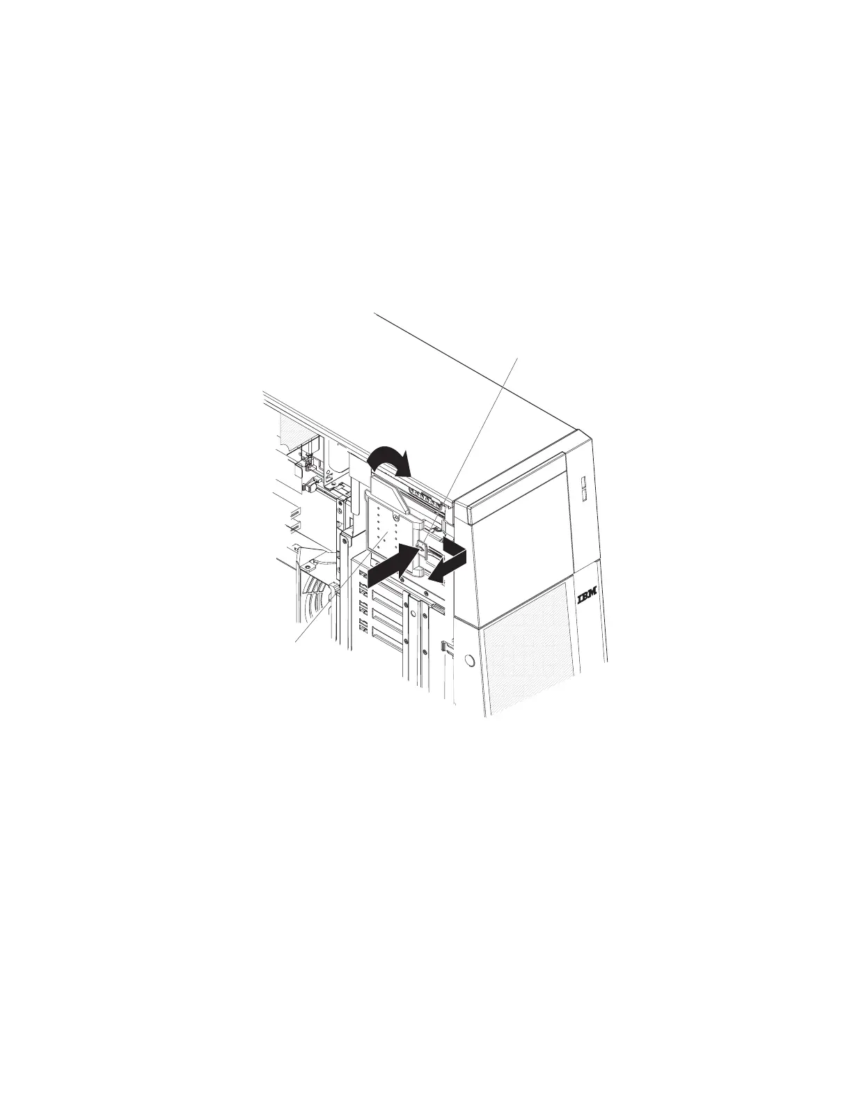
Light path diagnostics panel
To remove the light path diagnostics panel, complete the following steps.
Light path
diagnostics panel
Release Tab
1. Read the safety information that begins on page vii and “Handling
static-sensitive devices” on page 57.
2. Turn off the server and peripheral devices, and disconnect the power cords and
all external cable as necessary to replace the device.
3. Unlock and remove the left-side cover (see “Removing the left-side cover and
bezel” on page 57).
4. Disconnect the light path diagnostics panel cable from the system board.
5. Press in on the release tab and twist the light path diagnostics panel clockwise
until it stops; then, remove the panel from the server.
To install a replacement light path diagnostics panel, complete the following steps:
1. While you hold the cable out of the way, position the light path diagnostics panel
over the slots on the side of the drive bay cage.
2. Rotate the panel counter clockwise until it clicks into place.
3. Connect the cable to the system board.
Chapter 4. Removing and replacing server components 77
 Loading...