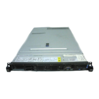
Microprocessor
release lever
Microprocessor
bracket frame
Microprocessor
dust cover
a. Press down and out on the release lever on the microprocessor socket
taking it out of the closed and locked position. Lift up the release lever until
it stops in the fully open position (approximately 135° angle) and the top
edge of the release lever has moved away from the microprocessor socket.
b. Lift the hinged microprocessor bracket frame into an open position.
Remove the microprocessor dust cover from the bracket frame. Store the
dust cover in a safe place.
5. Touch the static-protective package that contains the new microprocessor to
any unpainted metal surface on the server; then, remove the microprocessor
from the package.
Attention: Dropping the microprocessor during installation or removal can
damage the contacts. Also, contaminants on the microprocessor contacts, such
as oil from your skin, can cause connection failures between the contacts and
the socket.
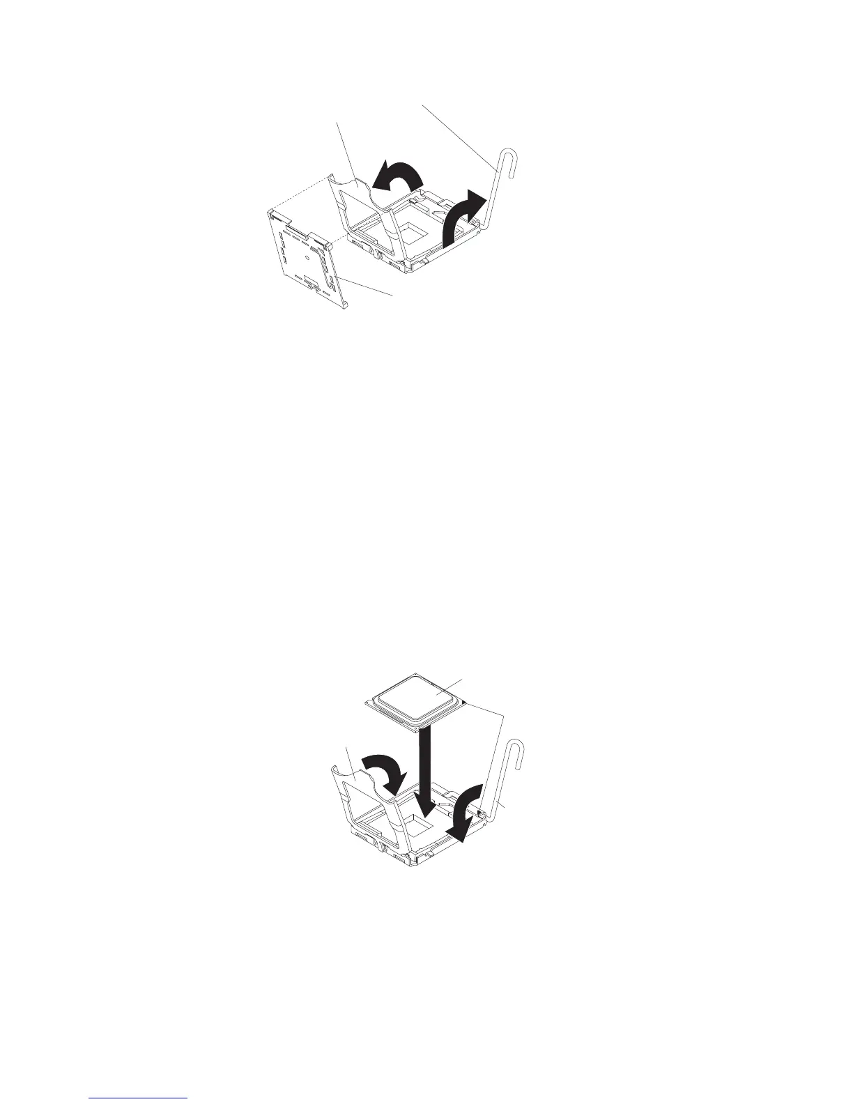
6. Position the microprocessor over the microprocessor socket. Use the triangular
alignment cutout on the microprocessor socket and the triangular alignment
mark on the microprocessor to assist you in aligning the microprocessor to the
socket. Then, carefully place the microprocessor into the socket. Do not force
the microprocessor, it only fits one way onto the socket.
Microprocessor
Alignment
marks
Microprocessor
socket dust cover
Microprocessor
release lever
7. Place the microprocessor bracket frame down over the microprocessor and the
microprocessor socket to secure the microprocessor position on the socket.
8. Rotate the microprocessor release lever into a closed position.
9. Place the heat sink on top of the microprocessor with the thermal grease side
down. Install the screws to secure the heat sink to the system board.
Attention: Do not touch the thermal grease on the bottom of the heat sink
after you remove the plastic cover. Touching the thermal grease will
contaminate it.
24 IBM System x3550 Type 7978: Installation Guide
 Loading...