(one flash per second), it indicates that the drive is being rebuilt. When the LED
is flashing rapidly (three flashes per second), it indicates that the controller is
identifying the drive.
v Hard disk drive activity LED: This LED is used on SAS hard disk drives. Each
hot-swap hard disk drive has an activity LED, and when this LED is flashing, it
indicates that the drive is in use.
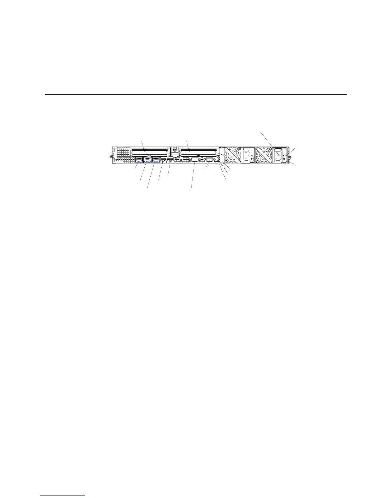
Rear view
The following illustration shows the connectors and LEDs on the rear of the server.
PCI slot 1 PCI slot 2
Video
connector
Serial
connector
USB 1
USB 2
Ethernet 1
Ethernet 2
Systems-
management
Ethernet connector
Power-on LED
AC power
LED
DC power
LED
System-locator LED
System-error LED
Power connector
v PCI slot 1: Insert a PCI Express type adapter into this slot.
v PCI slot 2: Insert a PCI Express type adapter into this slot. You can purchase an
optional PCI-X riser card assembly to convert this slot to accept a PCI-X adapter.
v Power connector: Connect the power cord to this connector.
v AC power LED: Each hot-swap power supply has an ac power LED and a dc
power LED. When the ac power LED is lit, it indicates that sufficient power is
coming into the power supply through the power cord. During typical operation,
both the ac and dc power LEDs are lit. For any other combination of LEDs, see
the Problem Determination and Service Guide on the IBM System x
Documentation CD.
v DC power LED: Each hot-swap power supply has a dc power LED and an ac
power LED. When the dc power LED is lit, it indicates that the power supply is
supplying adequate dc power to the system. During typical operation, both the ac
and dc power LEDs are lit. For any other combination of LEDs, see the Problem
Determination and Service Guide on the IBM System x Documentation CD.
v System-error LED: When this LED is lit, it indicates that a system error has
occurred. An LED on the light path diagnostics panel is also lit to help isolate the
error.
v Power LED: When this LED is lit and not flashing, it indicates that the server is
turned on. When this LED is flashing, it indicates that the server is turned off and
still connected to an ac power source. When this LED is off, it indicates that ac
power is not present, or the power supply or the LED itself has failed.
v Location LED: Use this LED to visually locate the server among other servers.
You can use IBM Director to light this LED remotely.
v Video connector: Connect a monitor to this connector. The video connectors on
the front and rear of the server can be used simultaneously.
v Serial connector: Connect a 9-pin serial device to this connector. The serial port
is shared with the baseboard management controller (BMC). The BMC can take
control of the shared serial port to perform text console redirection and to redirect
serial traffic, using Serial over LAN (SOL).
Chapter 3. Server controls, LEDs, connectors, and power 31
 Loading...