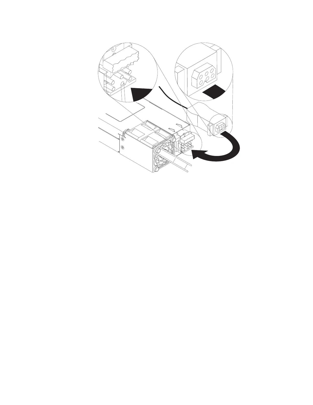
5. Insert the dc power cords into the power supplies.
a. Line up the triangular key on the dc power-cord connector with the triangular
notch on the power-supply connector.
b. Push the power-cord connector into the power-supply connector until it is
well seated.
6. Connect the other ends of the dc power cable to the dc power source. Cut the
wires to the correct length, but do not cut them shorter than 150 mm (6 in.). If
the power source requires ring terminals, you must use a crimping tool to install
the ring terminals to the power cord wires. The ring terminals must be UL
approved and accommodate 12-gauge wires. The minimum nominal thread
diameter of a pillar or stud type terminal must be 3.5 mm; for a screw type
terminal the diameter must be 4.0 mm.
The power cord consists of 6 wires (two black, two red, and two
green-and-yellow striped). Stack each same-colored pair of wires and attach
them to the same power source.
7. Make sure that the green power LEDs on the power supply are lit, indicating
that the power supply is operating correctly. The two power LEDs are on the left
of the power-cord connector.
Chapter 4. Removing and replacing server components 73
 Loading...