+5
Vdc
-Refresh
Refresh
Request
D
Q
8253-5
Clock
System
Bus
----+
Clear
Gate 0
Clock
In
0
+5
Vdc
Gate 1
Clock
In
1
I/O
Address
Hex
0061
Gate 2
Port
Bit
0
Clock
In
2
Clock
Out
0
8259A
IRQ
0
Clock
Out
1
Clock
Out
2
Low
To
Speaker
I/O
Address
Pass
Hex
0061
Fi 1
ter
Port
Bit
1
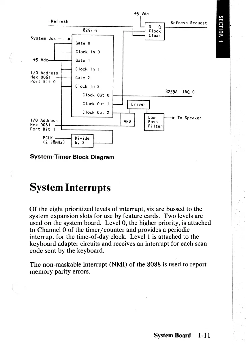
System-Timer
Block
Diagram
System Board 1-11
The
non-maskable interrupt (NMI) of the 8088
is
used to report
memory parity errors.
SystemInterrupts
Of
the eight prioritized levels of interrupt, six are bussed to the
system expansion slots for use by feature cards. Two levels are
used
on
the system board. Level 0, the higher priority,
is
attached
to
Channel 0
of
the timer/counter and provides a periodic
interrupt for the time-of-day clock.
Levell
is
attached to the
keyboard
adapter circuits and receives an interrupt for each scan
code
sent by the keyboard.
 Loading...