ii
MISCELLANEOUS ITEMS
The following parts are additionally required for instal-
lation, but are not supplied with the AT-140.
Purchase these parts locally.
q AWG 14 × 4 conductor shielded cable
•IcomoffersanoptionalOPC-1147/Nc o n t r o l c a b l e .
Length: 10 m (32.8 feet)
w 50 Ω coaxial cable
e Two PL-259 connectors
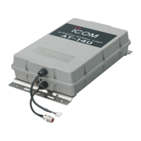
FEATURES
Weather resistant
The AT-140 is housed in a durable, completely
weather resistant ASA case, with a rubber gasket. The
antenna tuner can be conveniently installed near the
antenna element.
Matches all bands
The AT-140 matches all frequencies on the HF marine
band.Forexample,thetunermatchesa7m(23feet)
long-wire antenna across 1.6–30 MHz.
Full automatic tuning
Just push the [TUNE] key on the transceiver, and the
AT-140 immediately tunes for a minimum SWR on any
frequency in the HF marine band.
HF operation on any size ship
The AT-140 allows HF operation where antenna ele-
ment length is restricted due to space.
Simple installation
Installation is simple. Just connect the control and an-
tenna cables. You never need to open the cover.
45 memories for shorter tuning time
To decrease the tune-up time, the AT-140 automati-
cally stores the matching conditions for up to 45 fre-
quencies. Retuning a memorized frequency takes ap-
proximately 1 second.
Super capacitor for memory backup
Even if the AT-140 is not used for approximately 1
week, the built-in super capacitor backs up the con-
tents of the 45 memories.
Low power tune up
The AT-140 emits low output power during tuning. This
feature reduces the possibility of causing interference
to other stations.
Tuner Through function
The Tuner Through function is built into the AT-140.
This function helps improve receiver gain, depending
on the antenna element length used, and the operat-
ing frequency.
TABLE OF CONTENTS
FOREWORD …………………………………………… i
IMPORTANT …………………………………………… i
EXPLICIT DEFINITIONS …………………………… i
PRECAUTIONS ……………………………………… i
SUPPLIED ACCESSORIES ………………………… i
MISCELLANEOUS ITEMS…………………………… ii
FEATURES …………………………………………… ii
1 SYSTEM INSTALLATION ……………………… 1–2
Five Critical Points for a successful HF ■
installation ………………………………………… 1
Vessel ground connection ■ …………………… 1
Antenna and tuners ■ ……………………………… 2
The importance of grounding ■ ………………… 2
2 ANTENNA SYSTEM …………………………… 3–4
Antenna for ship ■ ………………………………… 3
Antenna for land operation ■ …………………… 3
Coaxial cable ■ …………………………………… 4
Ground and counterpoise ■ ……………………… 4
3 INSTALLATIONS ……………………………… 5–7
Installation outline ■ ……………………………… 5
Control cable ■ …………………………………… 5
PL-259 connector ■ ……………………………… 6
Waterproofing the antenna connection ■ ……… 6
Mounting ■ ………………………………………… 7
Cable connections ■ ……………………………… 7
4 CONTROL CABLE SIGNALS ………………… 8–9
Terminal information ■ …………………………… 8
Transceiver setting ■ ……………………………… 9
5 UNIT DESCRIPTION AND SPECIFICATIONS 10
Unit description ■ ……………………………… 10
Specifications ■ ………………………………… 10
6 INSTALLATION EXAMPLE …………………11–12
 Loading...