2001 NEW
3
5
INSTALLATIONS
2001 NEW 2001 NEW
Installation outline ■
q Connect the pins to the control cable and insert
into the supplied connector.
•Referto“Controlcable”asdescribedbelow.
w Connect and solder the PL-259 connector to the
coaxial cable.
Refer to page 6, “PL-259 connector.”
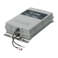
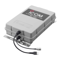
e Mount the AT-140 in the desired location.
•Refertopage7,“Mounting.”
r Connect the control and coaxial cables between
the transceiver and the AT-140.
•Refertopage7,“Cableconnections.”
t Connect the AT-140’s ground terminal to the ship’s
ground or counterpoise.
•Refer to page 3 “Antenna for ship,” and page 4
“Ground and counterpoise.”
y Connect the antenna element (wire).
•Refertoexamplesonpages2,11and12.
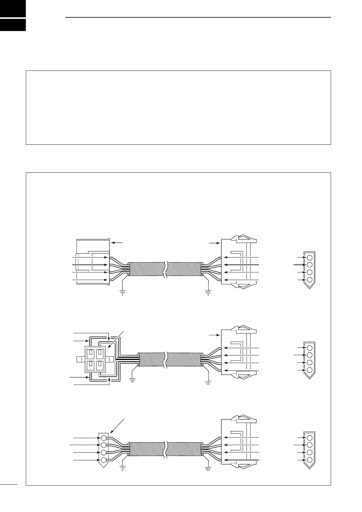
Between the AT-140 and HF transceiver, connect
four control signal lines, as shown below.
To prevent RF feedback, use a four conductor shield-
ed cable.
Connect the shield line to the [GND] terminal on the
transceiver.
Icom offers 10 m (32.8 feet) long control cables.
OPC-566: forIC-M710/RT,M700PRO
OPC-1147/N: forIC-M802
Refer to page 8, “Terminal information” for details.
[GND]
Use the optional OPC-1147/N, or
assemble a four conductor shielded
cable of the desired length using the
connector kits supplied with the
transceiver and the tuner.
[E] : Black
[13.6] : Red
[STAR] : White
[KEY] : Green
[KEY] : Green
[STAR] : White
[13.6] : Red
[E] : Black
Use the optional OPC-566/1147/N
(either connector of the AT-140 or
the transceiver requires assembly),
or assemble a four conductor
shielded cable of the desired length
using the connector kits supplied
with the transceiver and the tuner.
D When connecting to Icom IC-M802
D When connecting to Icom IC-M710/RT, IC-M700PRO
D When connecting to Icom IC-M700/TY, IC-78
[E] : Black
[13.6] : Red
[STAR] : White
[KEY] : Green
[GND]
[GND]
[GND]
To the AT-140
OPC-1147 OPC-1147N
[E] : Black
[13.6] : Red
[STAR] : White
[KEY] : Green
[GND]
To the AT-140
[E] : Black
[13.6] : Red
[STAR] : White
[KEY] : Green
[GND]
To the AT-140
[E] : Black
[13.6] : Red
[STAR] : White
[KEY] : Green
To the transceiver
To the transceiver
To the transceiver
Use the optional OPC-1147/N (this
connector only requires assembly),
or assemble a four conductor
shielded cable of the desired length
using the connector kits supplied
with the transceiver and the tuner.
OPC-1147 OPC-1147N
OPC-1147 OPC-1147N
Control cable ■
 Loading...