2001 NEW2001 NEW
6
3
INSTALLATIONS
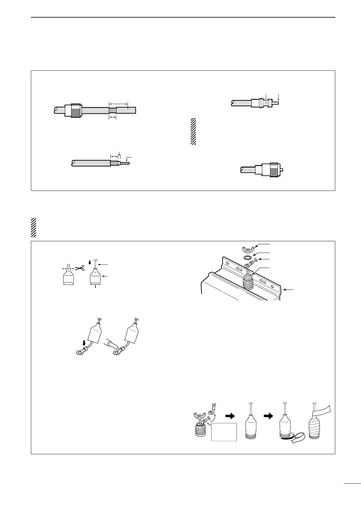
PL-259 connector ■
q Slide the coupling ring down.
Strip the cable jacket and tin the shield.
•Tintheexposedbraidandthenpulloutthejacket.
w Strip the cable as shown below.
Tin the center conductor.
e Slide the connector body over the cable and sol-
der it.
NOTE: Use a soldering iron with enough heating
power to securely solder the ground braid and
body. Otherwise the connection may be loose, and
communication trouble may occur.
r Screw the coupling ring onto the connector body.
Waterproofing the antenna connection ■
CAUTION: If you skip the following steps, moisture
will get into the connector, and this could damage
the antenna tuner.
q Cut off just the top of the weatherproof cap, and
pass the antenna wire through the cap.
Antenna wire
Weatherproof cap
w Insert the antenna wire into the opening of the
crimp-on wire terminal.
•Crimporsoldertheantennawire.
e Put the crimp-on wire terminal, star washer, and
wing nut on the base nut, in that order, then,
tighten the wing nut.
•Makesurethebasenutistightenedrmly,beforeyou
tighten the wing nut. (See the Fig.1 to the right.)
•Carefullybendthewireterminalup,afteryoutighten
the wing nut. (See the Fig.2 to the right.)
Fig.1
Wing nut
Crimp-on wire terminal
Star washer
Base nut
Antenna tuner
r Place the weatherproof cap over as much of the
insulator as possible.
•Howfardownitwillgodependsontheheightofthe
wing nut.
t Start wrapping the rubber vulcanizing tape at the
bottom of the insulator, then the weatherproof cap
and finally the antenna wire to prevent water seep-
ing.
•Wrapelectricaltape*overtherubbervulcanizingtape
to secure waterproofing.
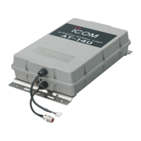
* The electrical tape is not supplied with the AT-140.
Fig.2
Insulator
e
t
r
Rubber
vulcanizing tape
Bend this part
up, AFTER
you tighten
the wing nut.
30 mm (1.2 inches) 10 mm (0.4 inches) 1–2 mm (0.04–0.08 inches)
 Loading...