4
2
ANTENNA SYSTEM
Coaxial cable ■
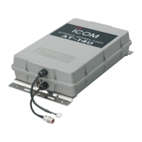
Insulate the lead-in cable of the AT-140 antenna termi-
nal and antenna element from other metal objects.
To prevent interference, keep cables as far as pos-
sible from an antenna, electric pump and other elec-
tronic equipment.
To prevent erroneous indications, keep cables as far
away as possible from the flux gate compass.
Use suitable noise filters for alternators or fluorescent
lights. Ask your dealer for details.
Ground and counterpoise ■
Why a ship’s ground is required D
The AT-140’s ground terminal MUST be connected
to your ship’s ground. Grounding prevents electric
shocks, interference to other equipment and other
problems. The AT-140 does not properly operate
without the grounding connections.
R DANGER! NEVER connect the ground termi-
nal to the following points. These connections may
cause an explosion or electric shocks:
•Gasorelectricalpipe
•Fueltankoroil-catchpan
IMPORTANT: The mounting plate is NOT con-
nected to the AT-140’s internal ground.
Ideal ground points D
One of following points is ideal:
•Ship’sground
•Externalgroundplate
•Externalcopperscreen/foil
Good ground points D
If electrically connected to sea water, one of the fol-
lowing points is usable:
•Stainlesssteelstanchion
•Throughmast
•Throughhull
•Metalwatertank
Undesirable ground points D
These connections may cause noise or electrolysis:
•Engineblock
•Ship’sDCbatteryground
Electrolysis D
All ground cables from the AT-140 or HF transceiver
on your ship should be connected to only one ship’s
ground.
DO NOT connect to two or more points. Voltage
difference between two or more ship’s grounds may
cause electrolysis.
DO NOT connect between dissimilar metals where
an electric current is present. These connections may
cause electrolysis.
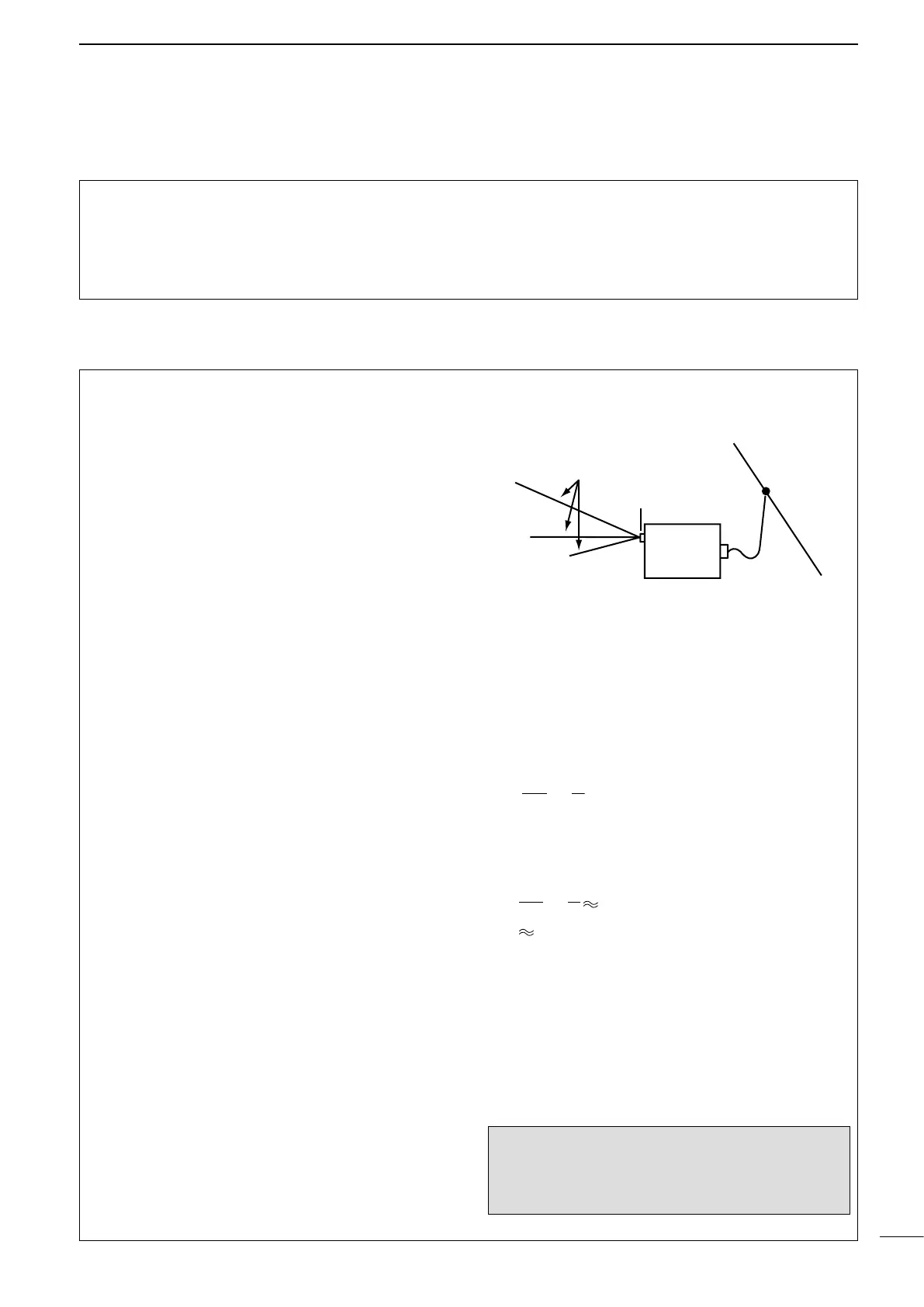
Counterpoise D
If your ship is made of FRP, etc. and a good ship’s
ground is not available, connect a counterpoise.
Ground terminal
AT-140
1
⁄
4
λ radial for
each band
1
⁄4λ (quarter wavelength) radial for each band is suit-
able for a counterpoise. Install the counterpoise di-
rectly below the AT-140’s ground terminal. Insulate
the ends of each radial from other metal objects.
Layout the radial horizontally and as straight as pos-
sible.
L :
Counterpoise length for the operating frequency [m]
f : Operating frequency [MHz]
[Example]
At an operating frequency of 16 MHz, use a counter-
poise with the following length:
L =
300
16
1
4
4.7 [m]
1 m
39 inches
×
Ground cable
For best results, use the heaviest gauge wire or
metal strap. Make the distance between the AT-140’s
ground terminal and ship’s ground as short as pos-
sible.
The supplied ground cable can be used for ground
connection through a mast. Confirm that the mast is
electrically connected to sea water.
R WARNING!— When grounding to metal hull
Use a Zinc anode to protect the hull from electroly-
sis. Ask your technical dealer or installer, or refer to
a technical book for RF ground details.
 Loading...