5
2
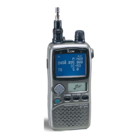
PANEL DESCRIPTION
i SKIP SCAN INDICATOR (pgs. 22, 24)
➥“"” appears when the selected memory channel is set
as a skip channel in memory mode.
➥“P"” shows that the skip frequency function is turned
ON or OFF in VFO mode.
➥“P"” appears when the selected memory channel is set
to be skipped during VFO scan (full, band and pro-
grammed scan) in memory mode.
o BATTERY INDICATORS
➥Both segments appear when the batteries have enough
capacity.
➥Only the right segment appears when the batteries are
nearing exhaustion.
•“Low V” appears when battery replacement is necessary and
the color LCD is ON.
•The U.S.A. version automatically turns itself OFF when the re-
ceiver detects that battery replacement is necessary.
!0 S (SIGNAL) INDICATORS
Show the relative signal strength while receiving.
!1 BUSY INDICATOR
“RX” appears when receiving a signal or when the squelch
is open.
!2 ATTENUATOR INDICATOR (p. 9)
Appears when the attenuator function is in use.
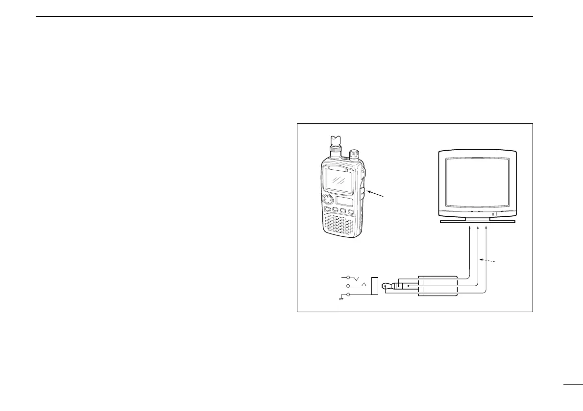
•Audio and video output jack information
•Video output impedance : 75 Ω, 1 Vp-p typical
•Audio output impedance : 1 kΩ, 300 mVrms typical
 Loading...