Home
Icom
Recording Equipment
DS-100 (#02)
Icom DS-100 (#02) User Manual
4
of 1
of 1 rating
36 pages
Give review
Manual
Specs
To Next Page
To Next Page
To Previous Page
To Previous Page
Loading...
offered by Busse-Yachtshop.com
21
5
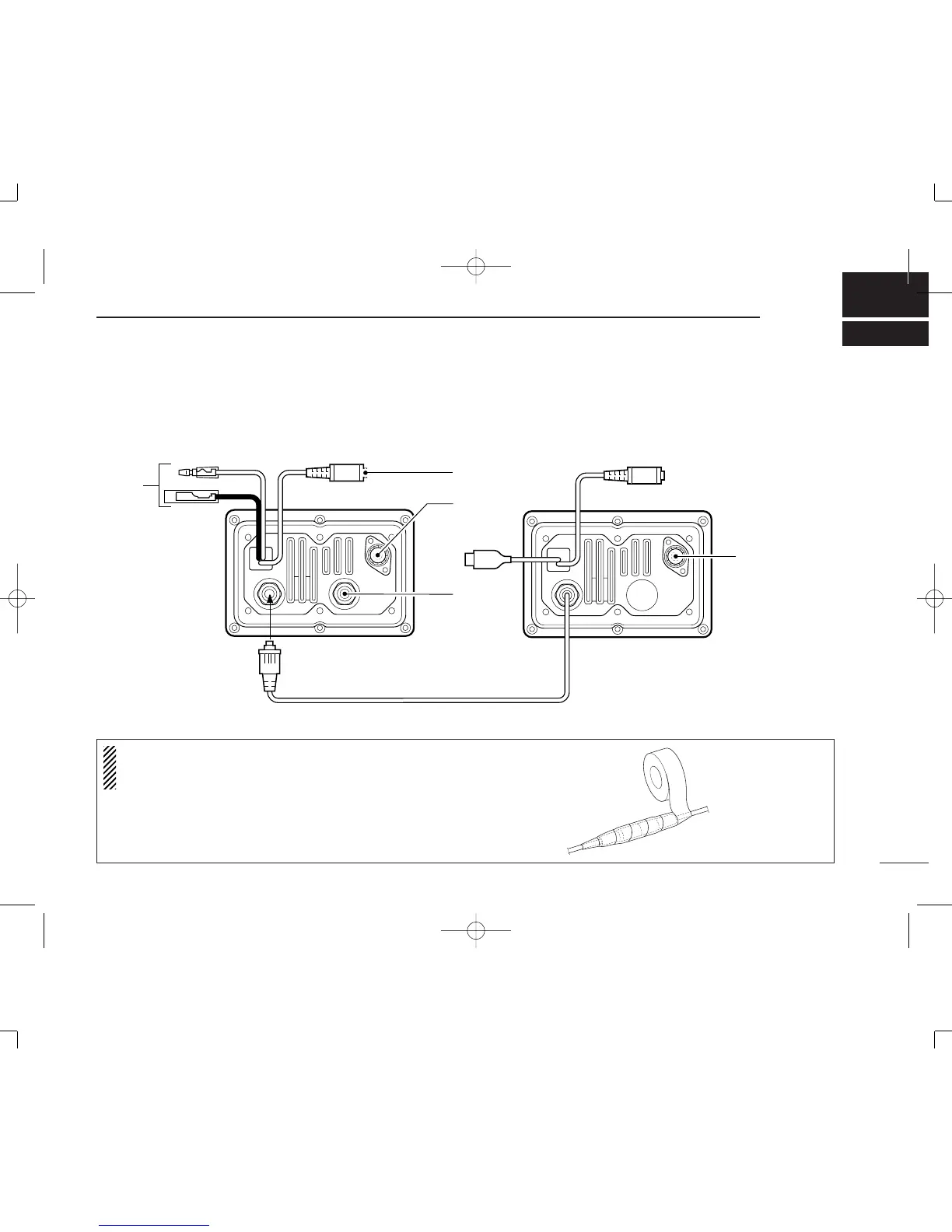
CONNECTIONS AND
INST
ALLA
TION
q
r
e
IC-M503
(or IC-M401EURO)
DS-100 (#02)
13.8V DC
GND
w
t
i
y
u
■
Connection diagram
(Connection exsample with IC-M503)
NOTE:
Binding the GPS cable, GPS connector
, clone re-
ceptacle, antenna connector with water-resistant tape, in
-
creases the waterproo
fi
ng of the controller
.
DS-100#02-(2) 01.12.13 10:53 AM Page 21 (1,1)
24
26
Table of Contents
Default Chapter
2
Foreword
2
Important
2
Explicit Definitions
2
Features
2
Cautions
3
Table of Contents
4
1 Panel Description
5
I Front Panel
5
I Function Display
6
2 Call Procedure
7
I Entry an MMSI
7
I Distress Call/Simple Operation
8
I Distress Call/Regular Operation
9
I Entry Position/Time
10
I Distress Call to Ships
11
I Individual Call
11
I Group Call
12
I All Ships Call
12
Call Procedure
12
3 When Receiving a Dsc Call
14
I When Receive a Distress Call
14
I Received Message
18
When Receiving a Dsc Call
21
4 Set-Up
22
I Select 'Set-Up
22
I Address ID
22
I Offset Time
24
I Brightness
24
I Contrast
24
I MMSI Check
24
5 Connections and Installation
25
I Connection Diagram
25
I Rear Panel Description
26
I Supplied Accessories
26
I Mounting
27
Connections and Installation
27
6 Vhf Marine Channel List
28
7 Specifications and Options
29
I Specifications
29
I Options
29
8 Dimensions
30
I Mb-75 Flush Mount Kit
31
9 Mb-75 (Option)
31
10 Template
33
11 Doc
35
4
Based on 1 rating
Ask a question
Give review
Questions and Answers:
Need help?
Do you have a question about the Icom DS-100 (#02) and is the answer not in the manual?
Ask a question
Icom DS-100 (#02) Specifications
General
Brand
Icom
Model
DS-100 (#02)
Category
Recording Equipment
Language
English
 Loading...