4
2
PANEL DESCRIPTION
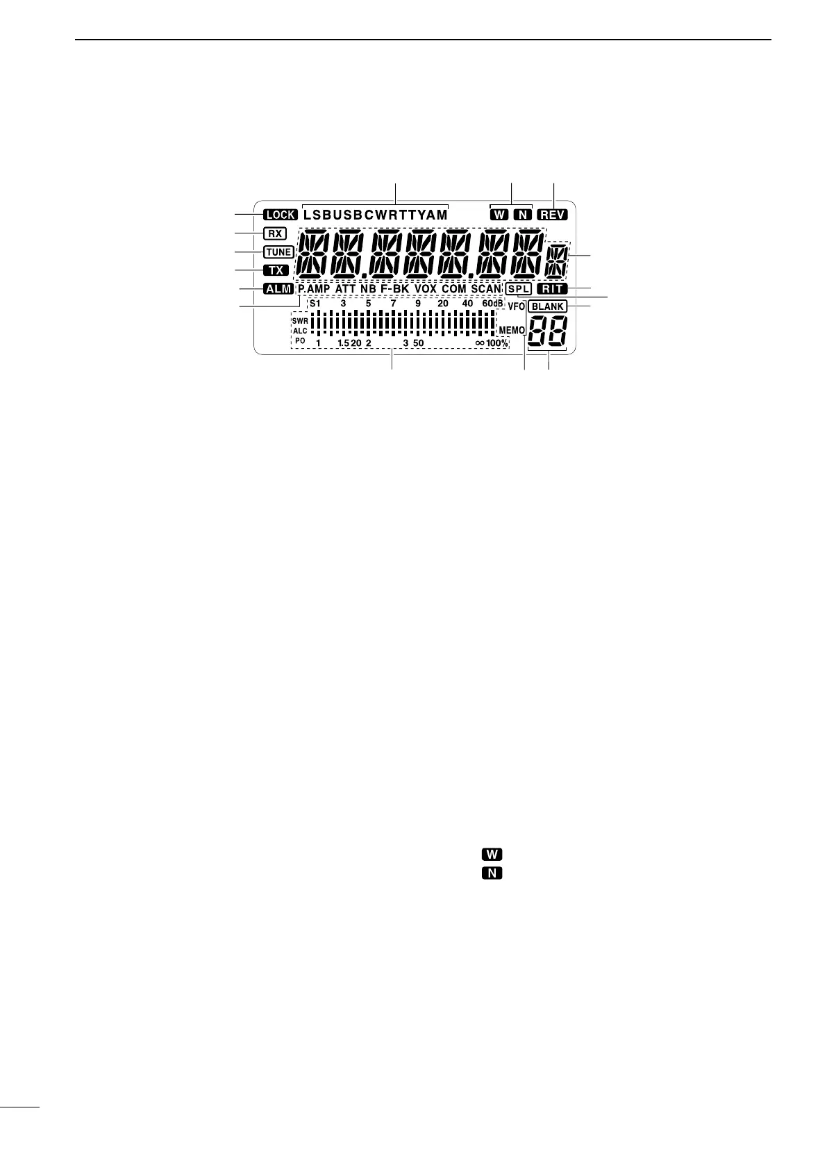
n Function display
q LOCK INDICATOR (p. 14)
Appears when the dial lock function is in use.
w RECEIVE INDICATOR
Appears while receiving a signal or when the
squelch is open.
e TUNE INDICATOR
➥ Appears or disappears when the connected au-
tomatic tuner is tuned completely, depending on
connected antenna tuner type.
➥ Flashes while tuning.
r TRANSMIT INDICATOR
➥ Appears while transmitting.
➥ Flashes while transmit frequency is indicated.
t ALARM INDICATOR
* This indicator appears only some versions.
Appears while 2-tone alarm is emitting or transmit-
ting
y FUNCTION INDICATORS
➥ “P.AMP” appears when preamp is activated.
➥ “ATT” appears when the RF attenuator is activat-
ed.
➥ “NB” appears when the Noise Blanker is activat-
ed.
➥ “BK” appears when the semi break-in function is
selected in quick set mode.
➥ “F-BK” appears when the full break-in function
activates in CW mode. (p. 23)
➥ “VOX” appears when the VOX function is select-
ed in quick set mode.
➥ “COM” appears when the speech compressor
activates in SSB mode.
➥ “SCAN” appears during scanning.
• Flashes when scan is paused.
u SIGNAL/SQL/RF-GAIN METER
➥ Functions as an S-meter while receiving.
➥ Functions as a Power, ALC or SWR meter while
transmitting. (p. 16)
i VFO/MEMORY INDICATOR
➥ “MEMO” appears during regular operation.
* This indicator appears only some versions.
➥ “VFO” appears during VFO operation.
o CHANNEL NUMBER READOUT (p. 13)
Shows the selected channel number.
!0 BLANK INDICATOR
Appears when no frequency programmed channel
is selected.
!1 SPLIT INDICATORS (p. 13)
Appears when the duplex channel, in which differ-
ent frequencies between transmit and receive are
programmed, is selected.
!2 RIT INDICATOR (p. 19)
Appears when the RIT function is in use.
!3 CHANNEL READOUT
Shows the memory names, or stored frequency of
the selected channel.
!4 REVERSE INDICATOR (p. 15)
Appears when the CW reverse or RTTY reverse
mode is selected.
!5
WIDE/NARROW FILTER INDICATORS (pgs. 21, 22)
➥
“ ” appears when the wide IF filter is selected.
➥ “ ” appears when the narrow IF filter is select-
ed.
!6 MODE INDICATORS (p. 15)
Indicates the temporarily selected operating mode.
 Loading...


