3 - 1
SECTION 3 CIRCUIT DESCRIPTION
While transmitting, serial-connected PIN diodes are ON,
thus the TX line is connected to the antenna, and the RX
line is connected to the GND simultaneously to prevent
transmit signal entering.
The attenuator functions as a part of the AGC circuit. The
AGC volatge which is applied to the PIN diodes controlls RX
signal level to enter the RX circuits.
The tuned-BPF is adjusted so that it responds to receiving
frequency and rejects all others, by the variable capacitor
whose capacitance is varied by applied voltage "T1" and
"T2."
The RF AMP amplifi es RX signals to a level suited to the 1st
mixer.
3-1 RECEIVER CIRCUITS
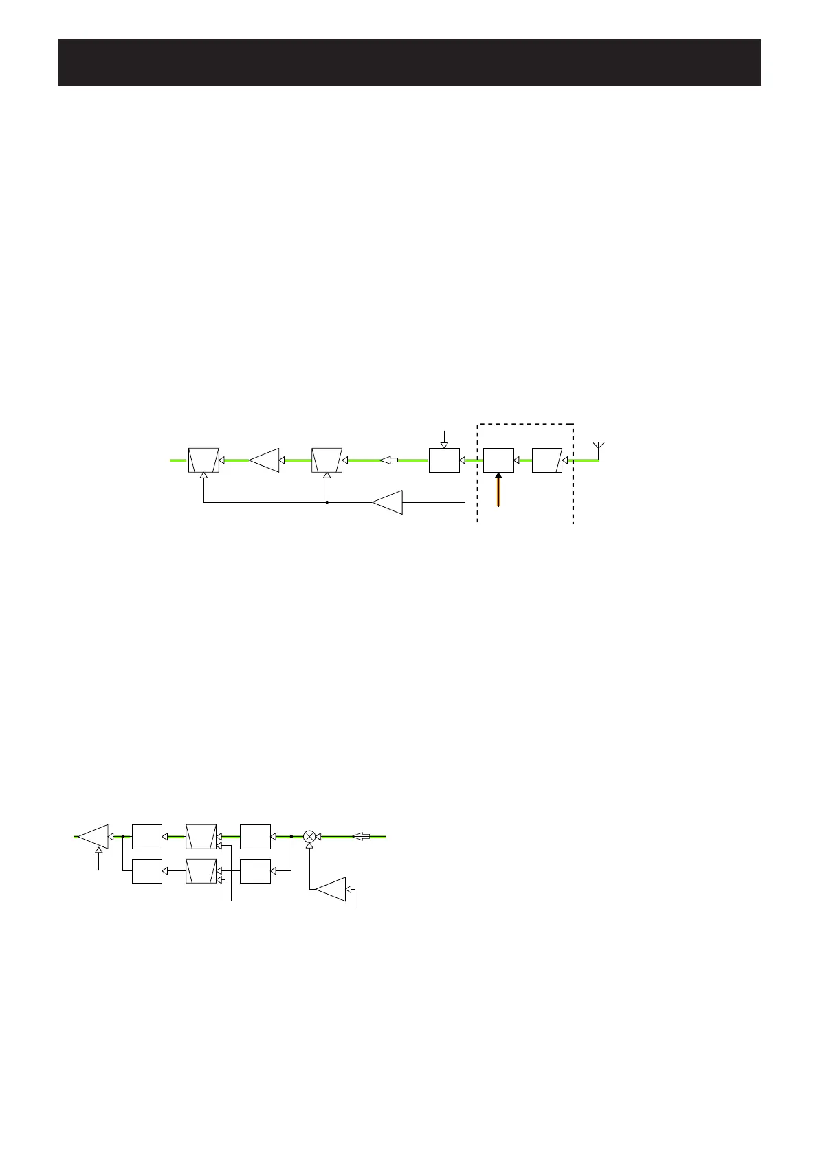
RF CIRCUITS
RF circuits consist of RF fi lters, antenna switch (ANT SW),
RF AMPlifi er (RF AMP), etc., and extracts and amplifi es the
signals of frequency which desired to receive.
The received signals (RX signals) from the antenna are
passed through the LPF, ANT SW (as an LPF in RX),
attenuator, and the two-staged tuned BPF.
The filtered RX signals are amplified by the RF AMP, and
passed through another two-staged tuned BPF. The fi ltered
RX signals are then applied to the 1st IF circuits.
The ANT SW toggles RX line and TX line. While receiving,
the TX line and the antenna is disconnected to prevent RX
signals entering. The RX line is disconnected from the GND
simultaneously, and an LPF which guides received signals
to the RX circuits is composed.
LPF
ANT
SW
ATTBPF
RF
AMP
BPF
ANT
BUFF
D1,D2,D3
D502, D503, D504
L521–L523,
C572,575,577,578,582
D10,D11,
L2,L4
IC69
D13,D14
L8,L10
PA UNIT
MAIN UNIT
TUNE1
IC52
RF_AGC
1ST IF CIRCUITS
The 1st IF circuits consist of 1st mixer, 1st IF fi lter and 1st
IF amplifier. And it converts the RX signals into the 1st IF
signal, then fi lters to remove unwanted signals and amplifi es.
The filtered RX signals are applied to the 1st mixer to be
converted into the 1st IF signal, by being mixed with the 1st
Local Oscillator (LO) signals from the RX VCO via buffer.
The converted 1st IF signal is passed through the 1st IF
fi lter (FI4 for AM RX, FI3 for WX RX) via fi lter switches, to
be removed unwanted signals. The filtered 1st IF signal is
amplified by the 1st IF AMP. The amplified 1st IF signal is
then applied to the 2nd IF circuits.
2ND IF AND DEMODULATOR CIRCUITS
The 2nd IF circuits consist of 2nd mixer, 2nd IF filter, 2nd
IF amplifier. And it converts the 1st IF signal into the 2nd
IF signal, then filters to extract 2nd IF signal only and
amplifi es. And the demodulator circuit converts the 2nd IF
signal to AF signals.
• AM signals
The amplified 1st IF signal is applied to the FM IF IC, and
converted into the 2nd IF signal, by being mixed with the
2nd LO from the X2, at internal 2nd mixer. The converted
2nd IF signal is filtered by external 2nd IF filter (FI5), and
amplified by three external 2nd IF AMPs. The amplified
2nd IF signal is AM-demodulated by Q21. A PN junction
construction inside Q21 is used for AM detection to obtain
low output impedance. The demodulated AF signals are
applied to the RX AF circuits via the ANL (Automatic Noise
Limiter) circuit which reduces pulse-type noises, when the
ANL function is activated.
BPF
XTALIF
AMP
Filter
SW
Filter
SW
Filter
SW
Filter
SWBPF
XTAL
BUFF
IC68
32
1st MIXER
D19
FI3 BW= 20 kHz
BW= 9 kHz
FI4
D2 7
D2 8
Q20
<1st IF=38.85 MHz>
FIL1
FIL2
D20
AGC_2
Q45
• RF CIRCUITS
• 1ST IF CIRCUITS

 Loading...


